
 English
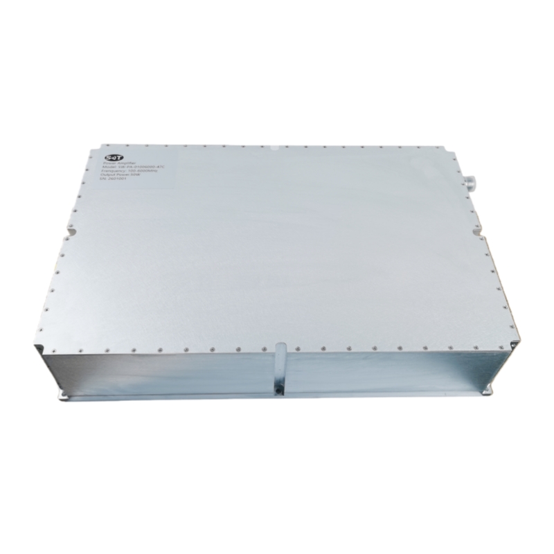
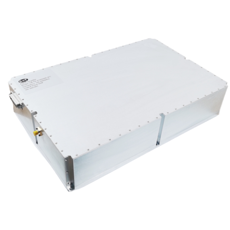
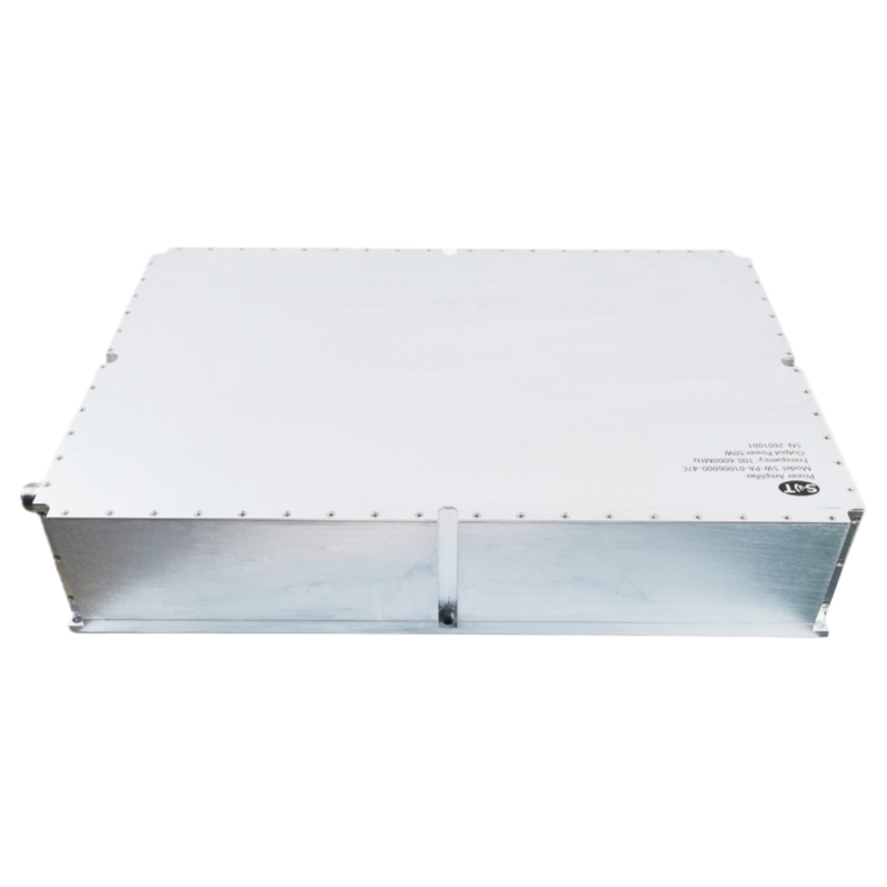
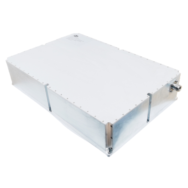


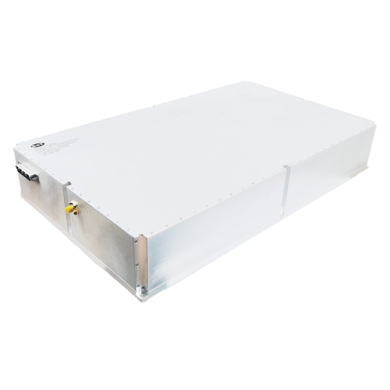
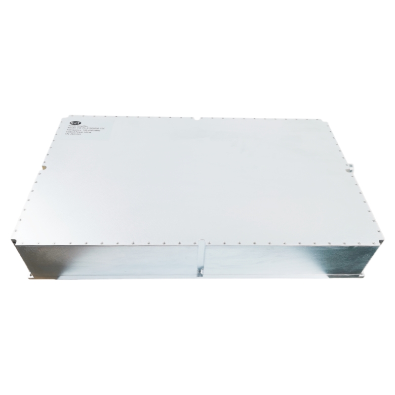
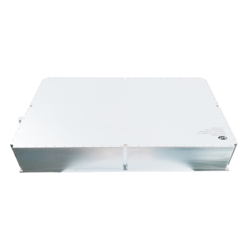
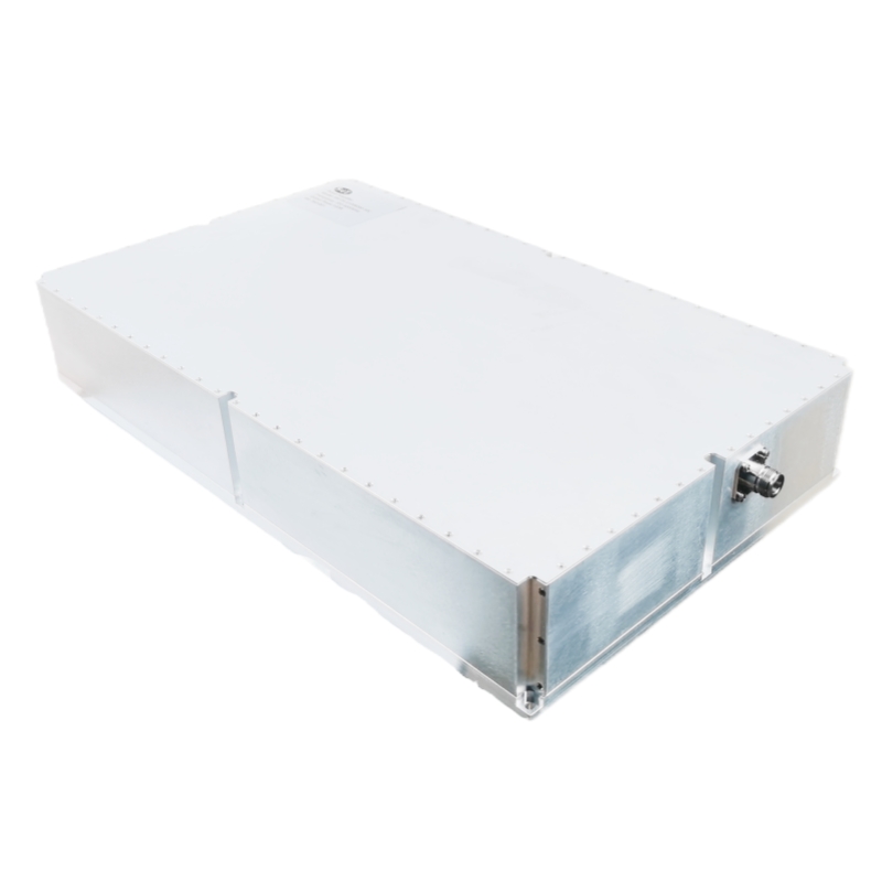
100–6000 MHz 100W Broadband RF Power Amplifier for Test, Jamming and Signal Amplification
Place of Origin:China
Brand Name:SWT
Model Number:SW-PA-01006000-50C
Price:Please Contact Customer Service
Product Description
1. Main Technical Specifications
qualification | code | Min | TYP | Max | Unit |
service frequency | BW | 100 | 6000 | MHz | |
saturated output power | Psat | 100 | W | ||
interiorinput power | Pin | 0 | dBm | ||
power gain flatness | ΔG | ±4 | dB | ||
power gain | Gp | 50 | dB | ||
Spurious suppression @Pout=50dBm | Spur | -50 | dBc | ||
Harmonic suppression @Pout=50dBm | 2nd/3nd | -20 | -10 | dBc | |
Enter the standing wave ratio | VSWRin | 2.0 | |||
input/output impedance | I/O-IMP | 50 | Ω | ||
supply electricity | Vdc | 28 | 30 | V | |
Power consumption @100W | Pdiss | 600 | 700 | W | |
operating temperature range | OT | -20 | +55 | ℃ | |
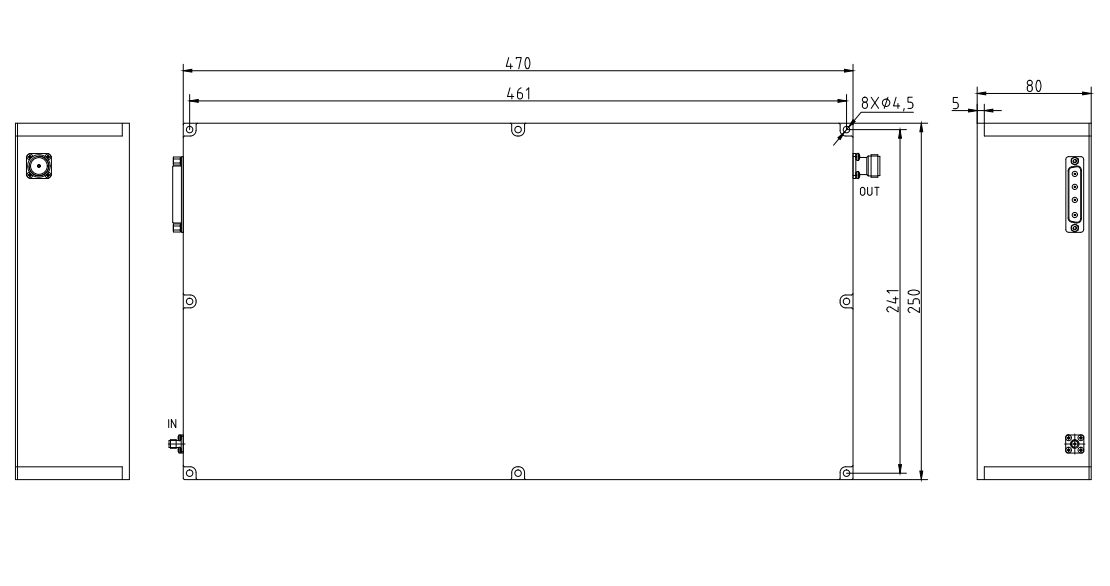
size | DM | 470×250×80mm³ | |||
weight | WT | No more than 15 kg | |||
heat radiation | Cooling | External radiator required for heat dissipation | |||
2. Interface Definition
interface code | interface type | interface function | remarks |
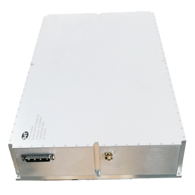
RFIN | SMA-K | radio frequency input | |
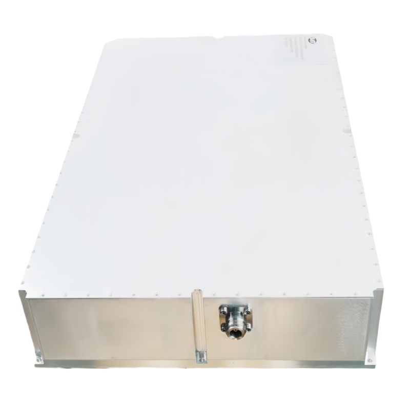
RFOUT | N-K | radio frequency output | |
DC | DSUB 4W4 male connector | power supply interface |
DSUB 4W4 Public Head Definition
pin | definition | function | remarks |
A1 | VDD | +28V | Power supply positive |
A2 | VDD | +28V | Power supply positive |
A3 | GND | GND | Power supply negative |
A4 | GND | GND | Power supply negative |
3. Dimensional drawing;
Product Details
Name:
Operating Frequency:
Psat Output Power:
Gain:
Input Vswr:
Power Gain Flatness:
Spurious Signals:
Harmonic Signals:
Operating Temp:
Application:
Transport Package:
Specification:
Payment & Shipping Terms
Minimum Order Quantity
1/pcs
Packaging Details
Standard Packing
Delivery Time
5-8 work days
Payment Terms
L/C, D/A, D/P, T/T, Western Union, MoneyGram
Supply Ability
100pcs per month
Send Inquiry