
 English
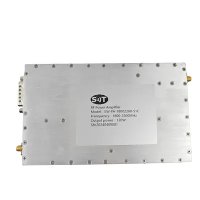
High Efficiency, Low Distortion 1.8-2.2GHz Gain 35dB Transmitter RF Power Amplifier for Wireless Networking
Place of Origin:China
Brand Name:SWT
Model Number:SW-PA-18002200-51C
Price:
Product Description
High Efficiency, Low Distortion 1.8-2.2GHz Gain 35dB Transmitter RF Power Amplifier for Wireless Networking
Description
The RF (Radio Frequency) Power Amplifier is an electronic device used to enhance the power of RF signals. It is primarily used in wireless communication, radar systems, satellite communication, broadcast television, medical equipment, and other fields. The amplifier can amplify low-power RF signals to sufficient levels to ensure signal integrity and prevent excessive attenuation during transmission.
RF power amplifiers typically use high-frequency electronic components such as transistors, power transistors (such as GaN, LDMOS, etc.), integrated circuits, etc., to amplify signals by increasing voltage or current. They have a wide operating frequency range, typically covering frequency bands from tens of kilohertz to several gigahertz, suitable for processing various RF signals.
In applications, RF power amplifiers play a crucial role in wireless communication systems, enhancing signal transmission distance, coverage range, and anti-interference capability. They also have significant applications in radar systems, broadcast television, satellite communication, and medical equipment.
Overall, RF power amplifiers are an indispensable component in modern wireless communication and electronic devices, providing reliable signal amplification solutions for various RF applications.
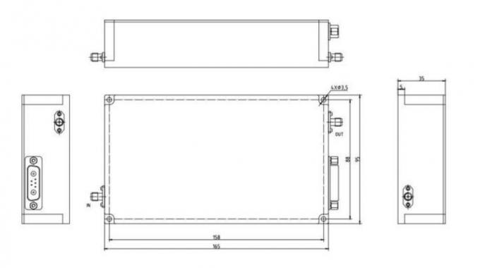
Outline Dimensional Drawing
Specification
| RF / ELECTRICAL | ||||
| PARAMETER | MIN | TYP. | MAX | UNIT |
| Operating Frequency | 1.8 | 2.2 | GHz | |
| RF INPUT | 0 | dBm | ||
| Power Gain | 50.8 | 51 | dB | |
| P-sat Output Power | 50.8 | 51 | dBm | |
| Power Gain Flatness | ±2 | dB | ||
| In/Out Impedance | 50 | Ω | ||
| Spurious Signals | -60 | dBc | ||
| Harmonic Signals | -20 | dBc | ||
| Operating Voltage | 28 | V | ||
| Currents | 8 | 9 | A | |
| Input VSWR | 2 | |||
| MECHANICAL | ||
| PARAMETER | VALUE | UNIT |
| Dimensions (W x D x H) | 165*95*35 | mm |
| RF Connectors (Input / Output) | SMA-KF / SMA-FK | -- |
| Control Connector | D-SUB:Power on/power off control; Monitoring parameters include output power, temperature |
-- |
| Cooling | Exteral Heatsink Required | -- |
| Weight | ≤2.5 | kg |
| ENVIRONMENTAL / PROTECTIONS | |||
| PARAMETER | MIN | MAX | UNIT |
| Operating Temp. | -20 | +55 | °C |
| Storage Temp. | -40 | +80 | °C |
| Amplifier Safeguard Temp. | +90 | °C | |
| Shock | MIL-STD-810F/G | ||
| Vibration | MIL-STD-810F/G | ||
| Protections | With over temperature protection, input over power protection, over voltage protection, over current protection | ||
| INPUT/OUTPUT panel Connector | |||
| AMPLIFIER CONNECTOR TYPE: | AMPLIFIER CONNECTOR TYPE: | ||
| TRIAD CABLE PART NUMBER: | TRIAD CABLE PART NUMBER: | ||
| NUMBER | NUMBER | NUMBER | |
| X1 | X1 | X1 | |
| X2 | X2 | X2 | |
| X6 | X6 | X6 | |
| Connector Definition | ||
| AMPLIFIER CONNECTOR TYPE: | D-SUB | |
| TRIAD CABLE PART NUMBER: | —— | |
| NUMBER | Definition | DESCRIPTION |
| 1 | VDD | 28V |
| 2 | GND | GND |
| 3 | PA Enable | TTL Hi= Enable, TTL Lo = Disable or No Connection |
| 4 | Alarm | Alarm (TTL) |
| 5 | Temp monitoring | Temperature (Analog) |
| 6 | NC | NC |
| 7 | NC | NC |
Product Details
Name:
1800-2200MHz RF Power Amplifier
Operating Frequency:
1800~2200MHz
Psat Output Power:
120W
Gain:
51dB
Input Vswr:
2
Power Gain Flatness:
±2dB
Spurious Signals:
-60dBc
Harmonic Signals:
-20dBc
Operating Temp:
-20~55°c
Application:
Communication,EMC Test,Electronic Warfare
Transport Package:
Carton
Specification:
165 x 95 x 35mm
Payment & Shipping Terms
Minimum Order Quantity
1/pcs
Packaging Details
Standard Packing
Delivery Time
5-8 work days
Payment Terms
L/C, D/A, D/P, T/T, Western Union, MoneyGram
Supply Ability
100pcs per month
Send Inquiry