 English

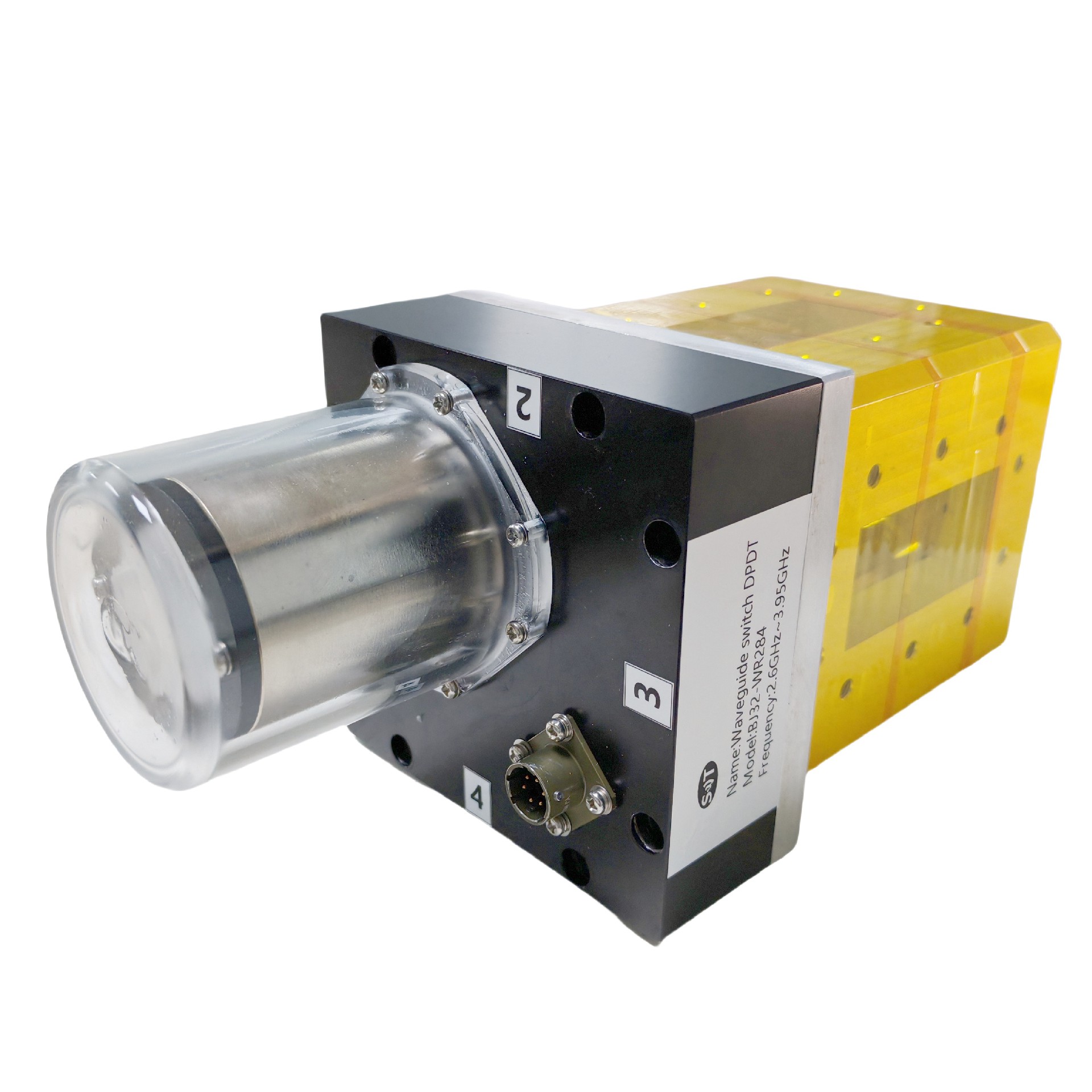


High-performance 2.6GHz to 3.95GHz Electric & Manual Waveguide Switches for communication systems, radar, and RF testing setups
Place of Origin:China
Brand Name:SWT
Model Number:BJ32-WR284
Price:
Product Description
High-performance 2.6GHz to 3.95GHz Electric & Manual Waveguide Switches for communication systems, radar, and RF testing setups
Product introduction
| Frequency range | 2.6GHz to 3.95GHz | VSWR | ≤1.1 |
| Insertion Loss | ≤0.1dB | Port isolation | ≥80dB |
| Port Switching | Dual Knife, Dual Throw | Switching time | ≤120mS |
| Voltage range | 24V±10% | Steady state current | ≤3A |
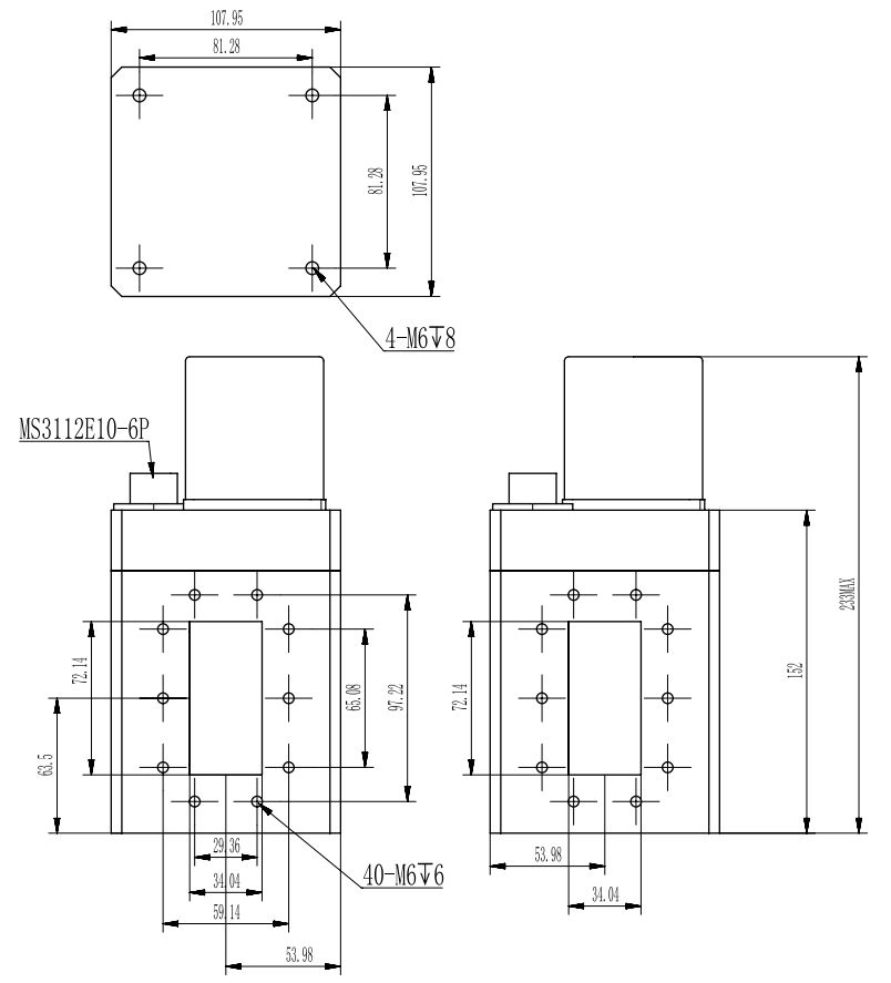
| Flange connection | FDP32 | Working temperature | -40~+85℃ |
| Storage temperature | -50~+80℃ | Working environment | outdoor, waterproof, salt spray prevention |
Table 1 MS3112E10-6P Connector Pin Description
Pin number | A | B | C | D | E | F |
use | Power supply +24V | Ground (electric connection) | Power supply +24V | Connecting microswitch | Microswitch Ground | Connecting microswitch |
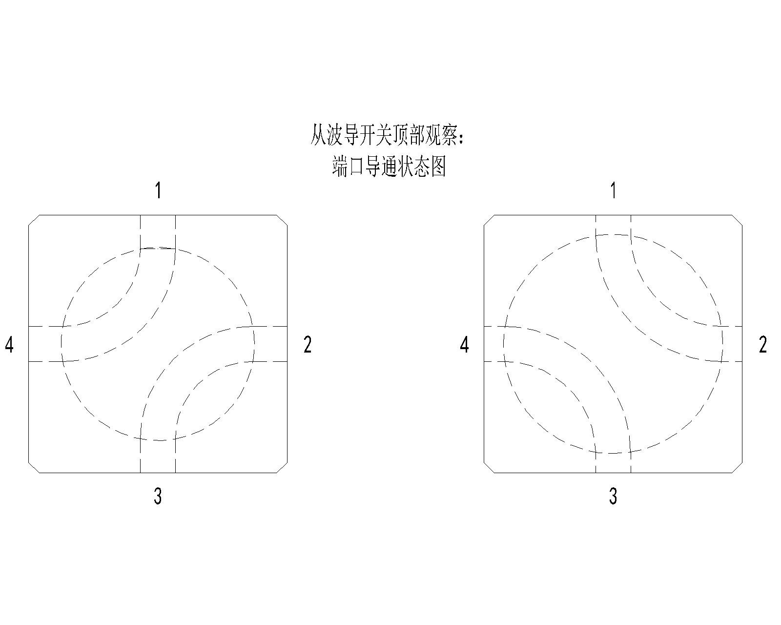
Table 2 Waveguide converter control wiring principle port signal definition
MS3112E10-6P | Signal Definition | instructions |
A | Power supply +24V | The switch switches the power supply and is in state Ⅰ (PORT1 and PORT4, PORT2 and PORT3 conductive) when A is connected to +24V for a duration of 120ms ± 20ms. |
B | Ground (electric connection) | |
C | Power supply +24V | The switch switches the power supply and is in state II (PORT1 and PORT2, PORT3 and PORT4 on) when C is connected to +24V for 120ms ± 20ms. |
D | Connecting microswitch | Switch state signal, when the switch is in state Ⅰ, pins D and E conduct. |
E | Microswitch Ground | Grounding is recommended. |
F | Connecting microswitch | Switch state signal,When the switch is in state II, pins E and F conduct. |
Product Details
Name:
2.6GHz to 3.95GHz Electric & Manual Waveguide Switches
Operating Frequency:
2.6GHz to 3.95GHz
Operating Voltage:
24V±10%
Connector Type:
lsolation:
≥80dB
Ins. Loss:
≤0.1dB
VSWR:
≤1.1
Application:
communication systems, radar, and RF testing setups
Payment & Shipping Terms
Minimum Order Quantity
1/pcs
Packaging Details
Standard Packing
Delivery Time
5-8 work days
Payment Terms
L/C, D/A, D/P, T/T, Western Union, MoneyGram
Supply Ability
100pcs per month
Send Inquiry

ADD:Rooms 405 & 406, 4th Floor, Building 2, Big Data Industrial Base, No. 180 Software Avenue, Yuhuatai District, Nanjing, Jiangsu Province, China
+86 17302591509
+86-25-87702669
Contat Us
Copyright © 2026 Nanjing Shinewave Technology Co., Ltd. All Rights Reserved. PRIVACY POLICY