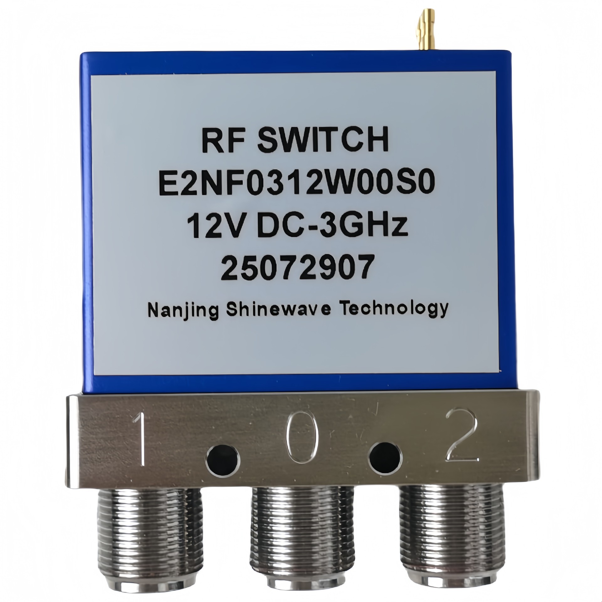
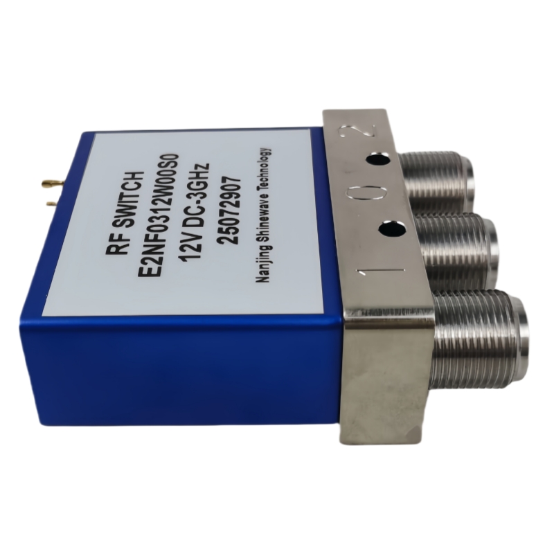
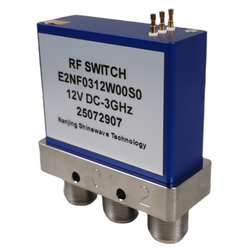
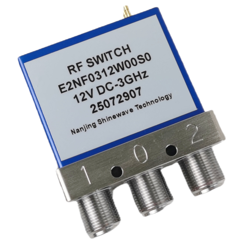
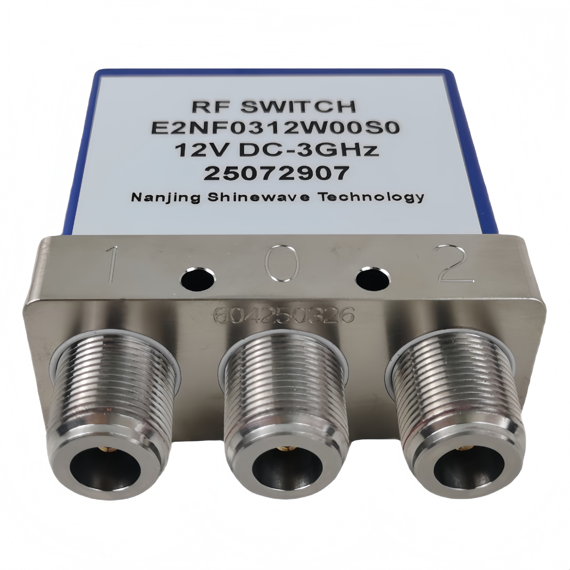
Product Functions
DC to 3GHz
Low loss, Low VSWR, High Isolation
N Female Connector
Selectable TTL driver control
RF Characteristics
Frequency (GHz) | Ins.loss (dB) | Isolation (dB) | VSWR | RF Power CW(W) |
DC-1 | 0.2 | 75 | 1.2 | 700 |
1-3 | 0.3 | 70 | 1.3 | 400 |
Operating Voltage/Coil Current
Operating Voltage(V) | 12 | 24 | 28 | |
Coil Current (mA) | Failsafe | 300 | 180 | 150 |
Latching | 320 | 180 | 150 | |
*It can be selected according to user requirements
TTL | TTL Low(V) | TTL High | |
0-0.3 | 3~5V | 20mA | |
Indicators | Withstand VoltageV (max) | CurrentcapacitymA(max) | Resistance Ω (max) |
50 | 100 | 15 |
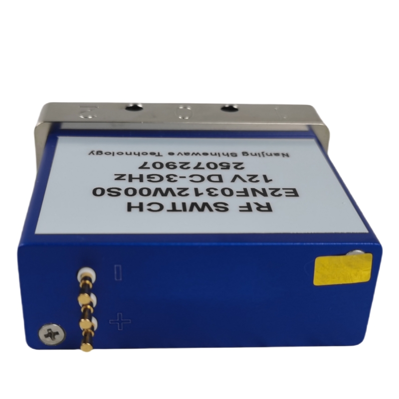
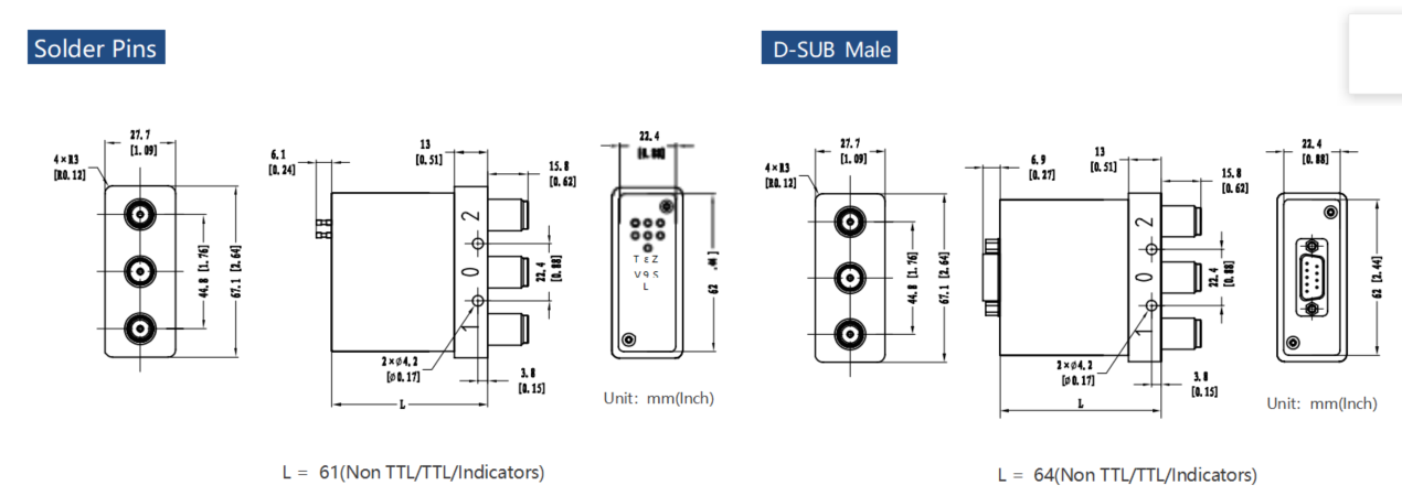
Outline Drawing
Specifications
Switching Sequence: Break before Make Switching Time: 15ms max Storage temperature: -55℃~85℃ Operating temperature: -25℃~65℃(Standard) -45℃ ~85℃(Extended1) -55℃~85℃(Extended2) | Mechanical Life Cycles: 2 million cycles RF Connectors: N Female Impedance: 50Ω | Mechanical Shock, Non-Operating: 50G、1/2 Sine、 11 ms Vibration Operating: 20-2000 Hz、10G RMS Actuator Terminals: Solder Pins/D-SUB 9Pin Male Weight: 250g |
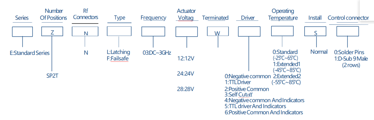
SPDT N 3GHz Truth Table/Product Selection

Truth Table
Failsafe Non TTL | |||||
Actuator Terminals | RF Connector | ||||
Solder Pins/D-SUB 9Pin Male | |||||
Pin No. | Define | No Power,RF 1-0 | |||
1 | V | RF 2-0 | |||
2 | N/A | - | |||
3 | GND | - | |||
4 | Ind.1 |
Indicators | RF 1-0 | ||
5 | Ind.2 | RF 2-0 | |||
6 | Ind.com | - | |||
7 | VDC | - | |||
8~9 | N/A | - | |||
Failsafe TTL | ||||||
Actuator Terminals | RF Connector | |||||
Solder Pins/D-SUB 9Pin Male | ||||||
Pin No. | Define | No Power,RF 1-0 | ||||
1 | VDC | RF 2-0 | ||||
2 | TTL | - | ||||
3 | GND | - | ||||
4 | Ind.1 |
Indicators | RF 1-0 | |||
5 | Ind.2 | RF 2-0 | ||||
6 | Ind.com | - | ||||
7~9 | N/A | - | ||||
Latching Non TTL | |||||
Actuator Terminals | RF Connector | ||||
Solder Pins/D-SUB 9Pin Male | |||||
Pin No. | Define | - | |||
1 | V1 | RF 1-0 | |||
2 | V2 | RF 2-0 | |||
3 | GND | - | |||
4 | Ind.1 |
Indicators | RF 1-0 | ||
5 | Ind.2 | RF 2-0 | |||
6 | Ind.com | - | |||
7 | VDC | - | |||
8~9 | N/A | - | |||
Latching TTL | |||||
Actuator Terminals | RF Connector | ||||
Solder Pins/D-SUB 9Pin Male | |||||
Pin No. | Define | - | |||
1 | VDC | ||||
2 | TTL | RF 1-0 | |||
3 | GND | - | |||
4 | TTL | RF 2-0 | |||
5 | Ind.1 | Indicators | RF 1-0 | ||
6 | Ind.2 | RF 2-0 | |||
7 | Ind.com | - | |||
8~9 | N/A | - | |||
Product Selection


Nanjing xinbo Technology co., Ltd.. fundada en 2008, es ® ¿ 39; Es una empresa especializada en investigación y desarrollo, producción y venta de componentes y subsistemas activos y pasivos de microondas de radiofrecuencia. Apoyándonos en el equipo de investigación académica de la Universidad de Aeronáutica y Astronáutica de nanjing, nuestra empresa ha establecido un equipo de I + D innovador con talentos de doctorado y maestría, atrayendo constantemente talentos sobresalientes de la industria y estudiantes sobresalientes de universidades conocidas, y ampliando el equipo.
Nuestra empresa tiene alrededor de 20 patentes de invención autorizadas en los campos de antenas reconfigurables de cambiadores de fase de dispositivos activos y pasivos. Las áreas de aplicación incluyen contramedidas electrónicas de radar, aeroespacial, navegación y otros campos militares. Al mismo tiempo, también es ampliamente utilizado en comunicaciones de microondas, comunicaciones móviles y otros productos del mercado civil, cubriendo componentes y antenas de dispositivos de microondas de radiofrecuencia, entre los cuales los productos activos incluyen amplificadores de potencia de microondas de estado sólido de alta potencia, módulos de recepción y recepción de amplificadores de bajo ruido, inversores ascendentes y descendentes, fuentes de frecuencia, etc. Los productos pasivos incluyen filtros de microondas, distribuidores de Potencia duplexores, acopladores, cosechadores de potencia, etc. Los productos de antena se basan principalmente en varias antenas de altavoz de alta ganancia, que cubren vhf, uhf, banda l, banda s, banda c, banda x, banda ku, etc.
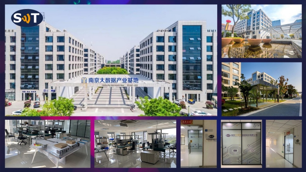
El nuestro; La compañía se encuentra en la hermosa antigua capital de las seis dinastías; Base industrial de Big data en el distrito de yuhuatai, nanjing. Para satisfacer las necesidades especiales de los clientes y los mayores requisitos de indicadores, además de los productos estándar, también ofrecemos a los clientes métodos personalizados de desarrollo de productos, dedicados a proporcionar a los clientes productos y servicios rápidos y de alta calidad.


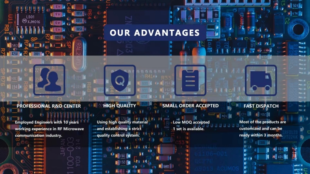


1.Nuestra ventaja
Apoyándose en el equipo de investigación académica de universidades conocidas, la compañía ha establecido un equipo de I + D innovador con doctorado y maestría; Talentos con título s, y absorber constantemente talentos sobresalientes de la industria y estudiantes sobresalientes de universidades conocidas para fortalecer la formación de equipos. La compañía tiene alrededor de 20 patentes de invención autorizadas en equipos de microondas, circuitos y antenas. Las áreas de aplicación incluyen radar, confrontación electrónica, aeroespacial.
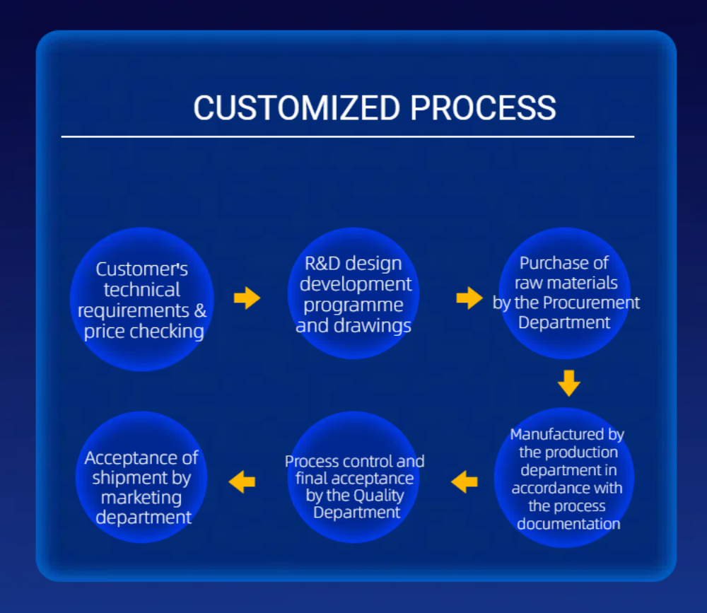
2.Sobre la personalización
Podemos personalizar de acuerdo con los requisitos del cliente ® ¿ 39; Requisitos de s, solo Díganos la frecuencia, la ganancia, la potencia.
3.Sobre el tiempo de entrega
Los productos personalizados suelen tardar entre 4 y 6 semanas y, si hay existencias, se pueden enviar dentro de 1 y 2 semanas.
4.Cómo garantizar la calidad
1)Control de calidad: detectar estrictamente si las materias primas y los procesos de producción cumplen con los estándares.
2) prueba de rendimiento: realizar pruebas funcionales y ambientales para verificar la salida de potencia y otros indicadores clave.
3)Garantía y soporte: proporcionar garantía y soporte técnico para resolver problemas durante el uso.
4)Auditoría de fábrica: realizar auditorías de calidad internas y de terceros regularmente.
5.Método de entrega
Si tiene su propio transitario, podemos enviarlo a la Agencia de carga designada por usted, y si no, podemos elegir los métodos de entrega más convenientes, como dhl, fedex, transporte aéreo y marítimo.
6.Método de pago
Cartas de crédito, facturas de aceptación, facturas de pago, transferencias bancarias, remesas de Western union, moneygram, paypal, alipay, bancos.

