
 English
Abstract:The UAV transmits data in the open space by data link.In the complex electromagnetic environment of the battlefield,UAV faces not only the mutual interference of its own multiple frequency equipment,but also the intentional interference of the enemy,even electronic countermeasure.The repeater-jamming will cause the data link performance of UAV to decline or fail.The simulation software is used to study the different parameters of repeater jamming.The influence of all kinds of parameters on the jamming effects are analayzed.On this basis,the anti-repeater jamming scheme is studied,and the bit error rates of uplink transmission of UAV are compared in different conditions of delay time,forwarded jamming power and SNR with anti-repeater jamming scheme.The effects of anti-repeater jamming method are verified by simulation.
0 Introduction
Unmanned Aerial Vehicles (UAVs) are widely used in various military fields such as reconnaissance and surveillance, electronic warfare, fire strike, and communication relay, making them important military equipment. Jamming and communication are always intertwined. The UAV uplink, operating in complex electromagnetic environments, is known as the UAV's "lifeline". The reliability of the UAV uplink not only determines the success of UAV missions but also directly affects the flight safety of the UAV . When the enemy employs repeater jamming, the deceptive signal transmitted by the enemy is similar in structure to the genuine signal from the ground control station (GCS) and may have higher power. This can largely cause the UAV to be unable to distinguish the genuine signal, mistakenly receiving the enemy's jamming signal. Consequently, the UAV might repeatedly execute a certain command, leading to loss of control or even being taken over by the enemy. Therefore, this type of deception jamming is not only more covert than barrage jamming but also its harmfulness cannot be ignored. Current countermeasures against repeater jamming mainly focus on alerting or detecting deceptive signals, and the application of many methods has significant limitations [3-4]. Once the UAV uplink is jammed or even controlled by the enemy, it may lead to irreversible consequences. Therefore, researching a method to counter repeater jamming to ensure the security of UAV uplink signal transmission is essential.
1 Characteristics of UAV Uplink
UAV data links complete communication between the ground control station (GCS) and the UAV through technologies like channel coding, modulation/demodulation, and information processing, transmitting formatted information in real-time according to predefined communication protocols. The UAV data link mainly consists of three parts: the ground control station (GCS), the UAV, and the wireless channel. The information transmitted via the UAV uplink primarily consists of remote control commands. Ground operators convey command intentions through the uplink to adjust the UAV's flight status, ensuring safe flight and completion of designated combat tasks. On the battlefield, UAV electronic information systems may face various electromagnetic threats, including electronic warfare and anti-radiation missile attacks. The main jamming styles can be categorized as: barrage jamming, deception jamming, and electronic interception.
UAV uplink data links typically employ spread spectrum anti-jamming technology and channel coding technology. Spread spectrum can be divided into Direct Sequence Spread Spectrum (DSSS), Frequency Hopping Spread Spectrum (FHSS), and hybrid spread spectrum. Spread spectrum technology is one of the most commonly used anti-jamming technologies in various data links. Satellite data links often use DSSS for their uplinks: a pseudo-random sequence code is added to the signal to spread its spectrum. At the receiver, the same code sequence is used for synchronous despreading to recover the original signal, during which the signal-to-noise ratio (SNR) is improved [8-10]. The difference between data links and general communication technologies lies in the data link's unified message format and communication protocol. Receiver processing technology typically employs signal demodulation, despreading, decoding, and other means to achieve this process. Channel coding technology is a method to combat unintentional interference by adding error-correcting code elements to reduce the bit error rate (BER) of signal transmission.
2 Working Principle of Repeater Jamming
Repeater jamming involves delaying the intercepted useful signal in the time domain, amplifying it, and then transmitting it to the receiving system. Its jamming signal is similar to the useful signal, belonging to a type of coherent jamming. Because the repeater jamming signal resembles the useful signal, it cannot be identified and is mistakenly received as the useful signal.
The basic concept of a repeater jamming system is shown in Figure 1. When the transmitter and receiver communicate, the signal from the transmitter is received by the receiver, which processes the received signal (including low-noise amplification, frequency conversion, filtering, decoding, decryption, etc.). If the signal transmitted by the transmitter is intercepted by the enemy, and the enemy copies and retransmits it, since characteristics like the signal frequency are highly similar to the signal transmitted by the transmitter, the receiver cannot distinguish it and mistakenly receives it as its own signal. This causes the UAV to malfunction or even leads to receiver blocking, preventing the reception of normal signals.
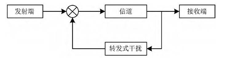
Fig.1 Schematic diagram of repeater jamming
The repeater jamming process mainly includes two parts: 1) Interception, storage, and processing of the link signal at the RF end; 2) Storage and forwarding of the baseband code stream sequence. The former involves technical issues such as high-sensitivity interception and reception of microwave signals at the RF front-end and data processing algorithms, which are difficult to implement. The key to the latter lies in the processing of the baseband code stream sequence. It corresponds to the baseband excitation code sequence obtained by modulo-2 addition of the remote control frame sequence and the spreading code sequence in the ground data terminal, containing the complete characteristics of the remote control signal link layer. Therefore, simulation design research on repeater jamming can be carried out by simulating the baseband code stream sequence.
3 Design of Anti-repeater Jamming Scheme
Since repeater jamming primarily causes interference by replaying the signal, that is, retransmitting the intercepted data unchanged to disrupt the UAV communication system, a sequence counting method is adopted to address this problem. The specific method is to insert a counting sequence into the header of the information frame. For the UAV uplink, this means that the signals sent by the ground station carry sequence numbers, and all signals are sent sequentially. However, the length of the information frame header is limited, meaning the sequence number range is finite. Since there may be numerous commands during a UAV mission, potentially causing insufficient sequence numbers, a cyclic sequence is used to solve the problem of insufficient frame header sequence numbers.
Considering the security of signals sent by the ground station, the signals are encrypted. Each frame of signal sent by the ground station has a corresponding key, and the UAV needs the corresponding decryption key to obtain the signal content. If a one-time pad is used (i.e., a different key for each command), the number of keys required on the UAV would be massive, making key management and replacement challenging problems. Combining with the cyclic sequence mentioned above, the method of using the same key for each cycle is adopted for management. This can both increase the security of signal transmission and reduce key generation.
Although each signal undergoes sequencing and encryption processing, repeater jamming itself involves delaying and forwarding the intercepted signal. If a signal with a small sequence number happens to pass the key verification, the UAV will still execute this jamming signal, affecting the normal execution of tasks. Therefore, an additional judgment is added when the UAV receives a signal: if the sequence number of the received signal is greater than the sequence number of the previously executed signal, the command signal is executed; conversely, if the sequence number of the received signal is less than or equal to the sequence number of the previously executed signal, the signal is not executed or is discarded. Through the above scheme, the probability of the UAV receiving and executing jamming signals is greatly reduced. Furthermore, if the UAV does not receive the latest signal sent by the ground station, but the command is forwarded by the repeater jammer and received by the UAV, it will not affect the normal execution of the UAV's task. The anti-repeater jamming model is shown in Figure 2.
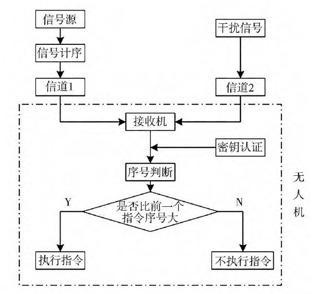
Fig.2 Anti-repeater jamming model
4 Model Construction
4.1 UAV Uplink Transmission System
The UAV uplink mainly consists of a transmitter, channel, and receiver. MATLAB/Simulink signal generator is used to generate binary random signals, which are then modulated using BPSK. This module primarily simulates the ground signal transmission system, processing the signals before sending them into the channel for transmission.
The UAV receiver primarily filters and demodulates signals transmitted by the ground station or forwarded by the repeater jammer, and then executes the commands contained in the signals. This module mainly simulates the UAV's signal processing system. All signals sent to the UAV undergo certain processing (including demodulation, decryption, decoding, etc.). Oscilloscopes, etc., are used to simulate the receiver.
4.1.1 Ground Station
The ground station module mainly generates binary random signals and then modulates them using BPSK modulation technology to facilitate transmission in the subsequent channel. This module primarily simulates the enemy ground signal transmission system, processing the signals before sending them into the channel for transmission. (Note: This description seems inconsistent with the context - it should be simulating the friendly GCS. The text says "敌方" (enemy), likely an error. It should be "己方" (friendly).)
4.1.2 UAV Receiver System
The UAV receiver system mainly filters and demodulates signals transmitted by the ground station or forwarded by the repeater jammer, and then executes the commands contained in the signals. This module primarily simulates the enemy UAV's signal processing system. (Note: This description seems inconsistent - it should be simulating the friendly UAV receiver. The text says "敌方" (enemy), likely an error. It should be "己方" (friendly).) All signals sent to the UAV undergo certain processing (including demodulation, decryption, decoding, etc.) to improve the security of the UAV system.
4.2 Bit Error Rate (BER) Calculation Module
The BER calculation module primarily measures the accuracy of data transmission, i.e., the frequency of bit errors. A higher value indicates a higher BER. This module is mainly used to measure the jamming performance of repeater jamming. A higher BER indicates that repeater jamming has a greater impact on the UAV's reception of correct signals. The jamming performance of repeater jamming is also affected by many other parameters, such as channel noise interference, repeater jammer power, and repeater jamming delay time.
4.3 Repeater Jamming Module
The repeater jamming module primarily performs low-noise amplification, frequency conversion, and power amplification on the received signal. The processed signal undergoes a certain delay before being retransmitted to the UAV receiver system. Since this process does not alter the content of the signal sent by the GCS but simply power-amplifies the intercepted signal to make it easier for the UAV to receive, it causes interference to the UAV.
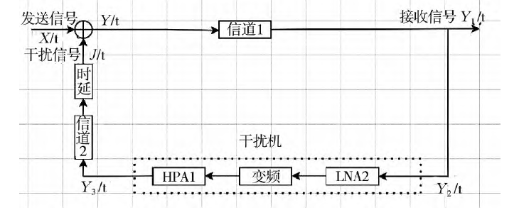
Fig.3 Repeater jamming mathematical model
Based on the principle of repeater jamming, the repeater jamming model shown in Figure 3 is established. Here, X(t) is the signal sent by Party A's GCS, Y(t) is the signal sent by Party B's GCS after being jammed, Y1(t) is the signal received by Party A's GCS, Y2(t) is the signal received by Party B's ground station, Y3(t) is the signal processed by Party B's ground station, and J(t) is the jamming signal.
The basic process is: The signal X1(t) sent by Party A's GCS is intercepted by Party B's ground station after attenuation through Channel 1, becoming Y2(t). Signal Y2(t) needs to be sent to Party A's UAV. However, during transmission to Party A's UAV, it passes through Party B's jammer, undergoing low-noise amplification, frequency conversion, and power amplification to become Y3(t), and simultaneously, after a certain delay, becomes the jamming signal J(t). The jamming signal J(t) is transmitted together with the next signal X2(t) sent by Party A's GCS to Party A's UAV, i.e., Y(t)=J(t)+X2(t). Meanwhile, signal X2(t) will similarly be processed like signal X1(t) to become a jamming signal interfering with Party A's UAV. This cycle repeats, continuously causing interference to Party A's UAV.
4.4 Anti-repeater Jamming Module
Based on the repeater jamming model, an anti-repeater jamming simulation model was established. Simulations were added mainly in four aspects: Sequence Number Module, Key Module, Verification Module, and Data Statistics Module, corresponding to the system's sequence counting, encryption, sequence number judgment, and data statistics functions, respectively.
4.4.1 Sequence Number Module
Compared to the original signal source module, this module adds a sequence number module. That is, based on the binary signal generated by the signal source, a binary sequence representing the sequence number is added in front, forming a new signal sequence for transmission. The maximum sequence number set in this model is 64. When a signal's sequence number reaches 64, the next signal's sequence number restarts from 1. Signals are generated in this cyclic manner.
4.4.2 Key Module
This module primarily encrypts the transmitted signal. The main method is to perform an XNOR operation between the binary signal carrying the sequence number and a new binary signal of the same bit length, obtaining an encrypted signal for transmission. To achieve the effect of changing the key once per cycle, the sampling time of this binary signal is set to 64 times the sampling time of the signal source. This ensures that a new key is used when the signal starts the next cycle. Simultaneously, symmetric key encryption is used for encryption. That is, the decryption end also uses the XNOR operation for decryption, allowing the original signal to be restored for the next step of signal judgment.
4.4.3 Verification Module
The primary function of the verification module is to judge the sequence number of the signal after it passes the encryption authentication. It extracts the first ten binary digits of the signal and compares them with the first ten binary digits of the previously received signal. If it is greater than the previous signal's first ten binary digits, the signal passes verification, and the command contained in the signal is executed. Otherwise, the signal is discarded.
4.4.4 Data Statistics Module
This module primarily collects five data items: The 1st item is the Bit Error Rate (BER), i.e., the proportion of erroneous signals among those passing verification; The 2nd item is the Reception Rate, representing the proportion of correct signals among those passing verification; The 3rd item is the number of signals that passed verification; The 4th item is the number of erroneous signals that passed verification, which can be understood as the number of mis-receptions; The 5th item is the Discard Count, i.e., the number of signals discarded for failing verification.
5 Simulation Analysis
Based on the above analysis of the repeater jamming model, simulations were conducted for communication scenarios both with and without repeater jamming, comparing the impact of repeater jamming on UAV signal reception. Parameters significantly affecting the effectiveness of repeater jamming were also analyzed.
5.1 Comparison with and without Repeater Jamming
Simulation parameters and conditions were set as follows: Signal modulation/demodulation method: BPSK; Delay time: T=1 s; Repeater Jammer: LNA (Low-Noise Amplifier): K1=1 dB; HPA (Jammer Power): K2=10 dB (using Saleh model); Channel: AWGN channel; SNR: K3=10 dB. The BER result analysis is shown in Figure 4.
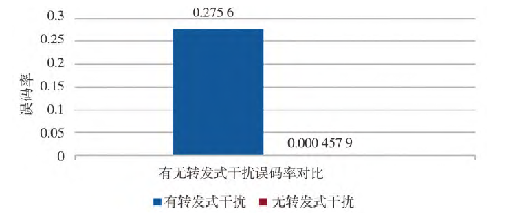
Fig.4 Comparison of bit error rates between with repeater jamming and without repeater jamming
The experimental results show that without repeater jamming, the BER was approximately 4.58×10⁻⁴. After adding repeater jamming, the BER increased to 2.76×10⁻¹. The BER with repeater jamming was 600 times higher than without. This demonstrates that repeater jamming significantly impacts the correct reception of UAV signals.
5.2 Factors Affecting Repeater Jamming Effectiveness
Based on the transmission characteristics of the UAV uplink, factors affecting repeater jamming effectiveness were analyzed mainly from the following three aspects.
5.2.1 Delay Time
Simulation parameters and conditions for different delay times: Signal modulation/demodulation method: BPSK; Repeater Jammer: LNA (Low-Noise Amplifier): K1=1 dB; HPA (Jammer Power): K2=10 dB (using Saleh model); Channel: AWGN channel; SNR: K3=10 dB. Keeping the above parameters constant and varying the delay time, the system transmission BER was obtained after multiple trials at each delay time, as shown in Figure 5.
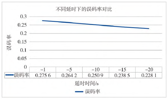
Fig.5 Bit error rates at different time delays
Analysis of the above experimental results shows that delay time has a certain impact on repeater jamming. As the delay time increases, the BER decreases, indicating that the jamming effect weakens.
5.2.2 Repeater Jammer Power
Simulation parameters and conditions for different repeater jamming powers: Signal modulation/demodulation method: BPSK; Delay time: T=1 s; Repeater Jammer: LNA (Low-Noise Amplifier): K1=1 dB; HPA (Jammer Power): using Saleh model; Channel: AWGN channel; SNR: K3=10 dB. Keeping the above parameters constant and varying the repeater jammer power, the results after multiple trials at each jamming power are shown in Figure 6.
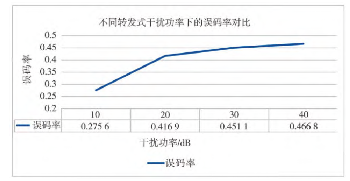
Fig.6 Bit error rates at different powers of repeater jammer
Simulation results show that repeater jamming power has a significant impact on jamming effectiveness. As the jamming power increases, the BER also increases. Furthermore, the rate of change in BER is greater in the 10~20 dB jamming power range compared to the 20~40 dB range. The analysis suggests that as the repeater jamming power increases, the likelihood of the UAV receiving the repeater jamming signal increases, leading to a higher probability of executing erroneous commands. However, as jamming power continues to increase, the UAV uplink receiver's reception capability is limited, performing amplitude limiting and filtering on the signal, hence the rate of change in BER decreases.
5.2.3 Channel Parameters
Simulation parameters and conditions for different SNRs: Signal modulation/demodulation method: BPSK; Delay time: T=1 s; Repeater Jammer: LNA (Low-Noise Amplifier): K1=1 dB; HPA (Jammer Power): K2=10 dB (using Saleh model); Channel: AWGN channel. Keeping the above parameters constant and varying only the SNR, the transmission BER was obtained after multiple trials at each SNR, as shown in Figure 7.
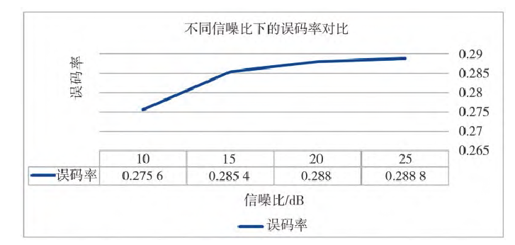
Fig.7 Bit error rates at different signal to noise ratios
It can be seen that as the SNR of the communication channel increases, the BER also continuously increases. That is, a higher output SNR from the jammer results in better jamming effectiveness against the entire UAV uplink. As the SNR increases, the rate of change in BER gradually slows down, indicating a non-linear relationship.
5.3 Anti-repeater Jamming Simulation Analysis
For repeater jamming, its impact on effectiveness was analyzed mainly from three aspects: delay time, repeater jammer power, and channel parameters. It was concluded that increasing jammer power and output SNR enhances interference against the UAV uplink, but increasing jammer delay time reduces the impact on the uplink. For the anti-repeater jamming model, its anti-jamming effectiveness is similarly analyzed from these three aspects.
5.3.1 Delay Time
Simulation parameters and conditions: Signal modulation/demodulation method: BPSK. Considering sequence cycling and key change, the sampling time of the key signal generator is set to 64 times that of the source signal generator; Repeater Jammer: LNA (Low-Noise Amplifier): K1=1 dB; HPA (Jammer Power): K2=10 dB (using Saleh model); Channel: AWGN channel; SNR: K3=10 dB. Simulation results are shown in Figure 8.
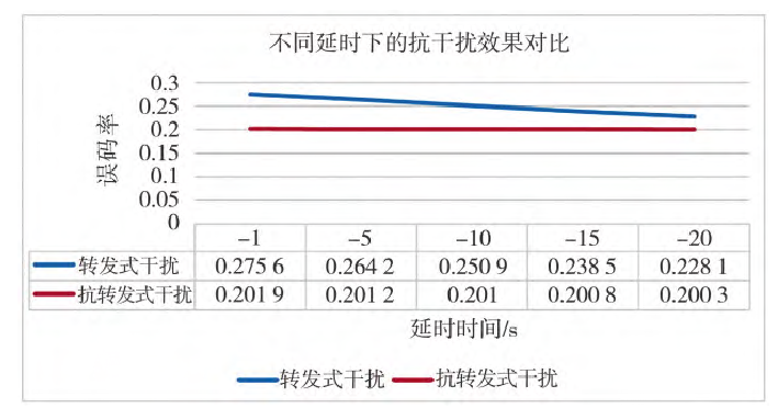
Fig.8 Comparison of anti-jamming at different time delays
Figure 8 shows the simulation results comparing the BER of the communication link under repeater jamming and the BER after applying the anti-repeater jamming scheme, at different delay times.
Simulation results from the previous section showed that the repeater jamming BER decreases as the delay time increases. It can be seen that after applying the anti-repeater jamming scheme, the communication link BER shows a significant decrease at a 1s delay. As the delay increases, the BER of the communication link using the scheme remains basically around 0.2. Moreover, the BER of the communication link using the anti-repeater jamming scheme is always lower than that without the scheme. This demonstrates that the anti-repeater jamming scheme achieves a certain effect, reducing the BER of the communication link.
5.3.2 Repeater Jamming Power
Simulation parameters and conditions: Signal modulation/demodulation method: BPSK. Considering sequence cycling and key change, the sampling time of the key signal generator is set to 64 times that of the source signal generator; Delay time: T=1 s; Repeater Jammer: LNA (Low-Noise Amplifier): K1=1 dB; HPA (Jammer Power): using Saleh model; Channel: AWGN channel; SNR: K3=10 dB. Simulation results are shown in Figure 9.
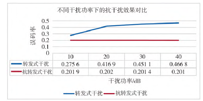
Fig.9 Comparison of anti-jamming at different jamming powers
Figure 9 compares the repeater jamming BER and the anti-repeater jamming BER under varying repeater jamming power conditions. From the previous section, it is known that the BER of the communication link under repeater jamming increases as the repeater jammer power increases. Figure 9 shows that after applying the anti-repeater jamming scheme, the BER of the communication link remains around 0.2. As the jammer power increases, the communication link BER remains essentially unchanged and is lower compared to the repeater jamming BER in all cases. This indicates that the anti-repeater jamming scheme achieves a certain effect.
5.3.3 Channel Parameters
Simulation parameters and conditions: Signal modulation/demodulation method: BPSK. Considering sequence cycling and key change, the sampling time of the key signal generator is set to 64 times that of the source signal generator; Delay time: T=1 s; Repeater Jammer: LNA (Low-Noise Amplifier): K1=1 dB; HPA (Jammer Power): K2=10 dB (using Saleh model); Channel: AWGN channel. Simulation results are shown in Figure 10.
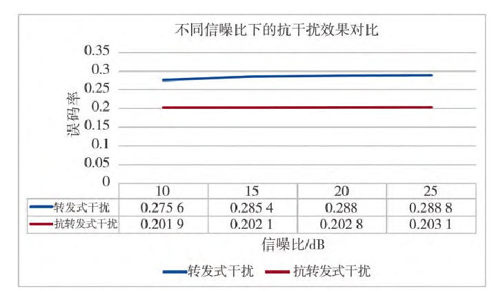
Fig.10 Comparison of anti-jamming at different signal to noise ratios
Figure 10 compares the repeater jamming BER and the anti-repeater jamming BER under varying channel parameters (SNR). From the previous section, it is known that increasing the SNR of the jamming signal channel increases the repeater jamming BER. After applying the anti-repeater jamming scheme, as the channel SNR increases, the communication link BER slightly increases, but its overall level remains lower than that of the communication link without the scheme. This indicates that the anti-repeater jamming scheme achieves a certain effect.
6 Conclusion
The UAV uplink is crucial for flight safety. Repeater jamming, which uses jamming equipment to send signals similar to the UAV data link based on uplink data characteristics, can disrupt normal communication between the UAV and the ground control station. More seriously, it may allow the enemy to take control of the UAV uplink. Therefore, an anti-repeater jamming communication scheme was designed. This involves adding sequence numbers to signals before transmission from the ground control station, with the sequence numbers cycling within a certain range. Each cycle corresponds to a single key, reducing the number of keys required during the entire UAV mission. Subsequently, signals must pass both key authentication and sequence number magnitude judgment. Only signals passing both verifications will be executed by the UAV system. MATLAB/Simulink was used to model and simulate the proposed anti-repeater jamming scheme. Comparing the UAV uplink transmission BER under different delay times, repeater jamming powers, and SNR conditions, the simulation results show that after applying the anti-repeater jamming scheme, the BER of the communication link decreases under various simulation conditions. This demonstrates that the scheme can enhance the anti-jamming capability of the UAV uplink to a certain extent.
 Research on an Anti-repeater Jamming Method of UAV Uplink.pdf