
 English
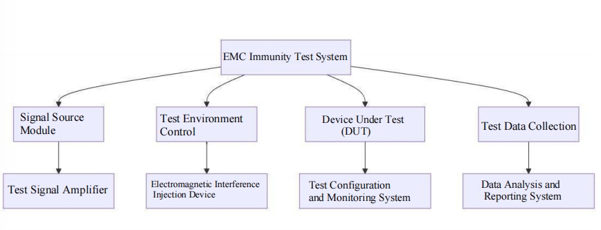
The Electromagnetic Compatibility (EMC) immunity test system evaluates the performance of electronic devices under external electromagnetic interference. The main objective is to verify whether the device can maintain functional integrity in a specific electromagnetic environment. A complete EMC immunity test system typically consists of the following major components:
Signal Sources
Signal sources generate the required interference signals, commonly including RF signals, pulse signals, or power frequency magnetic field signals:
l RF signal sources: For radiated immunity tests (e.g., IEC 61000-4-3 standard).
l Pulse signal sources: For fast transient/pulse immunity tests (e.g., IEC 61000-4-4 standard).
l Power signal sources: For power frequency magnetic field immunity tests (e.g., IEC 61000-4-8 standard).
Power Amplifiers
Power amplifiers amplify the signal from the signal source to a sufficient level to drive the load or interfere with the equipment. For example, RF immunity tests require high-power RF signals, and the amplifier's performance directly affects the test's accuracy and range.Coupling/Decoupling Networks (CDN)
CDNs couple interference signals to the equipment under test (EUT) while protecting other devices from interference. They are a core component of conducted immunity tests.Antennas or Probes
For radiated immunity tests, antennas radiate RF signals with specific electromagnetic field strengths around the device under test. Standard field strengths include 3 V/m, 10 V/m, or higher.Test Space and Shielded Rooms
EMC immunity tests usually require shielded or anechoic chambers to prevent external signals from interfering with test results and to ensure the test environment meets relevant standards.Monitoring Equipment
Oscilloscopes, spectrum analyzers, and power meters monitor signal characteristics, power levels, and interference signal accuracy.Equipment Under Test (EUT) and Auxiliary Equipment
The EUT is the test object whose functionality is monitored under interference. Auxiliary equipment assists the EUT in performing normal operations.
Selection and Use of Power Amplifiers
Power amplifiers are critical components of EMC immunity test systems. Their selection and use depend on specific test requirements, including:
Key Parameters for Selecting Power Amplifiers
l Frequency Range: The amplifier's frequency range must cover the test standard's specified band. For example, the IEC 61000-4-3 standard typically covers 80 MHz to 1 GHz and sometimes extends to over 6 GHz.
l Output Power: Determines the achievable field strength. For example, producing a 10 V/m field strength at a 3-meter test distance requires output power in the tens to hundreds of watts.
l Linearity: High linearity ensures minimal distortion in the output signal, meeting testing accuracy requirements.
l VSWR Tolerance: The amplifier must tolerate reflected power from non-ideal loads such as antennas.
Usage Notes for Power Amplifiers
l Thermal Management: Amplifiers generate significant heat during high-power output, requiring cooling systems (e.g., air or water cooling) for stable operation.
l Input Signal Control: Ensure input signal amplitude stays within the amplifier's allowable range to avoid nonlinear distortion or damage.
l Protection Measures: Verify the amplifier has overload, overheating, and reflected power protection to prolong its lifespan.
l Calibration and Validation: Calibrate the amplifier's output power and verify its accuracy before testing.
Common Power Amplifier Frequency Bands and Power Outputs
Different EMC immunity tests require specific frequency bands and power outputs for power amplifiers:
RF Amplifiers
Frequency Range: 80 MHz–1 GHz (standard testing range); extendable to over 6 GHz.
Output Power: 10 W–200 W for various field strength requirements.
Applications: RF radiated immunity tests (e.g., IEC 61000-4-3).
Microwave Amplifiers
Frequency Range: 1 GHz–40 GHz.
Output Power: 1 W–50 W.
Applications: High-frequency immunity tests and specialized microwave equipment tests.
Broadband Power Amplifiers
Frequency Range: 10 kHz–6 GHz (broadband applications).
Output Power: 50 W–500 W.
Applications: General EMC tests, covering multiple frequency bands.
Low-Frequency Power Amplifiers
Frequency Range: DC–10 MHz.
Output Power: 100 W–1 kW.
Applications: Power frequency magnetic field immunity tests and low-frequency conducted immunity tests.
Summary
The EMC immunity test system is an essential tool for evaluating device electromagnetic compatibility. Its core structure includes signal sources, power amplifiers, CDNs, and antennas. Power amplifiers play a key role in test systems, and their selection must consider frequency range, output power, and linearity. Common power amplifiers cover applications from low-frequency to high-frequency scenarios, providing critical technical support for EMC tests. Scientifically selecting and maintaining power amplifiers can significantly improve test efficiency and accuracy.
 Structure of EMC Immunity Test System.pdf