 English
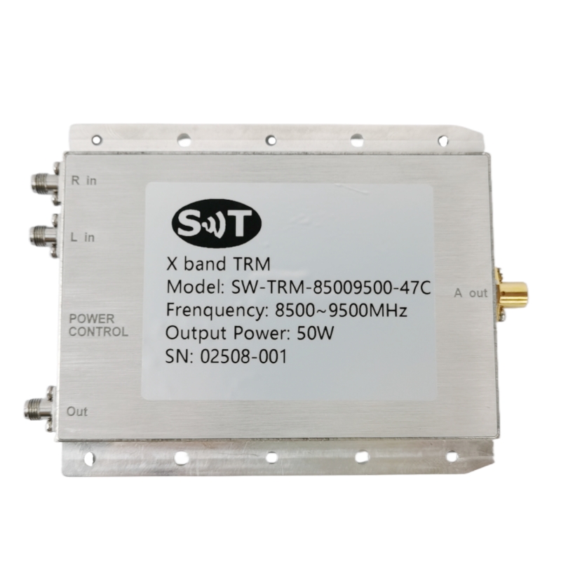

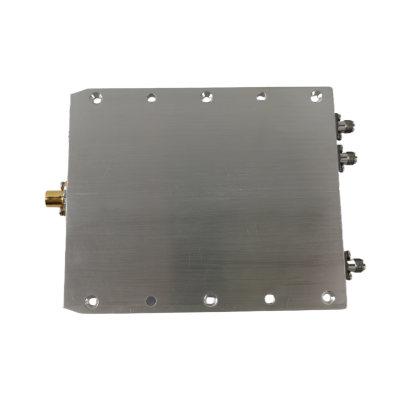
X-Band Transmit/Receive (TRM) Module 1-Channel 50W 8500~9500MHz Peak Power for Industrial Microwave Systems & Defense Radar
Place of Origin:China
Brand Name:SWT
Model Number:SW-TRM-85009500-47C
Price:Please Contact Customer Service
Product Description
Description
TRM stands for Tx /Rx Module, The module consists of 01 TX/RX Channel, TRM controller, Health
Monitoring and Power supply card. The TRM will have Tx input port 、 Tx output/RX input ports 、 Rx output ports and LO input port .
Specification
Typical performance at +28V DC +25oC, and in a 50Ω system.
RF / ELECTRICAL | ||||
PARAMETER | MIN | TYP. | MAX | UNIT |
Operating Frequency | 8500 | 9500 | MHz | |
No . of Tx / Rx Channel | 1 | |||
Peak Output Power / Channel | 47 | dBm | ||
Transmit Gain @ In all frequency/temps. | 45 | dB | ||
Tx input Power | 2 | 6 | dBm | |
Second Harmonic of TX | < -25 | dBc | ||
Period | 1200 | us | ||
Pulse Width | 0.5 | 300 | us | |
Max Duty Cycle | 25 | % | ||
Pulse Droop | <0 .5 (For 300 us pulse width) | dB | ||
Fall Time | 150 | ns | ||
Raise Time | 150 | ns | ||
Phase Shifter Settling Time | <150 | ns | ||
Transmit Channel Output ON/OFF Ratio | >110 | dBc | ||
Power Added Efficiency | 25 % | |||
Phase Shifter | 6 bits | 0 ~ 360 ° | ||
Phase Shifter Accuracy | < 5 °(RMS) | |||
VSWR (TX IN, ANT IN, RX OUT Ports) | 1.8:1 | |||
Rx Gain | 50 | dB | ||
Rx Output P1dB | ≥10 | dBm | ||
RX Input P1dB | -15 | dBm | ||
Rx Noise Figure(0 dB Attenuation State) | 4 | dB | ||
Rx Noise Figure(15 dB Attenuation State) | 6 | dB | ||
Receiver Channel Image Rejection | >25 | dBc | ||
Receiver Output in Band Spurious Rejection | >60 (Measured for +8 dBm output power) | dBc | ||
Receiver Output Out of Band Spurious/Harmonics Rejection | >50 (Measured for +8 dBm output power) | dBc | ||
Attenuator | 6 bits | 0~31.5 dB | ||
Attenuator Accuracy | < 1.7 (RMS) | dB | ||
Maximum Phase Change of Receiver Channel vs Attenuator States | <15 ° | |||
LO Input Power Level | 0 | 4 | dBm | |||
LO In to Transmit Out Isolation | <70 | dB | ||||
LO In to Receive Out Isolation | ≥70 | dB | ||||
Transmit Input to Receiver Output Isolation | >50 | dBc | ||||
Max . Rx tolerable power | ≥50W | Max duty cycle | ||||
Power Supply | 28 +5-5 | V | ||||
Average currents | 2 | A | ||||
Peaking currents | 8 | A | ||||
MECHANICAL | ||
PARAMETER | VALUE | UNIT |
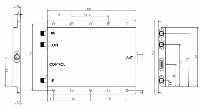
Dimensions (L x W x H) | 120 x 100 x 11 | mm |
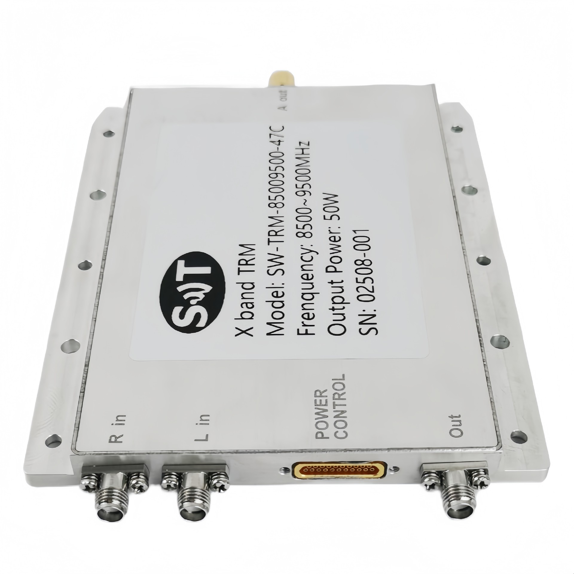
RF Connectors (Input / Output) | BMA/SMA-K ×3 | -- |
DC /Control Connector | J30J – 21ZK | -- |
Weight | ≤500 | g |
ENVIRONMENTAL / PROTECTIONS | |||
PARAMETER | MIN | MAX | UNIT |
Operating Temp. (Housing Temp.) | -33 | +70 | °C |
Humidity Range | 0-100 | % | |
PA Baseplate Shutoff Temperature | + 80 | °C | |
Connector Definition | |
AMPLIFIER CONNECTOR TYPE: | J30J – 21ZK |
TRIAD CABLE PART NUMBER: | —— |
NUMBER | DESCRIPTION |
1, 12,2, 13 | +28V |
3, 14,4, 15 | GND |
5 | SEL |
16 | R |
6 | Load |
17 | T |
7 | Data |
18 | CLK |
8,9, 19 | GND |
10 | Monitor voltage of Temperature |
21 | -5V |
11,20 | +5V |
 2025-08-25
Product Details
Packing:
Power Consumption:
Data Format:
Working Temperature:
Physical Interface:
Communication Interface:
Receiving Signal:
Applications:
Payment & Shipping Terms
Minimum Order Quantity
1/pcs
Packaging Details
Standard Packing
Delivery Time
5-8 work days
Payment Terms
L/C, D/A, D/P, T/T, Western Union, MoneyGram
Supply Ability
100pcs per month
Send Inquiry

ADD:Rooms 405 & 406, 4th Floor, Building 2, Big Data Industrial Base, No. 180 Software Avenue, Yuhuatai District, Nanjing, Jiangsu Province, China
+86 17302591509
+86-25-87702669
Contat Us
Copyright © 2026 Nanjing Shinewave Technology Co., Ltd. All Rights Reserved. PRIVACY POLICY