 English
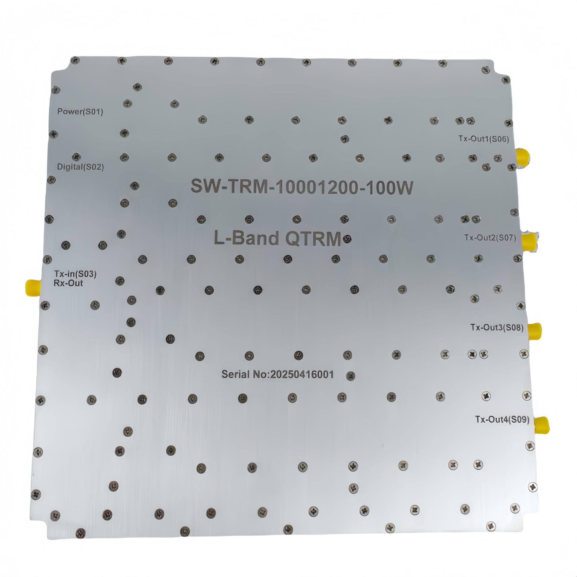
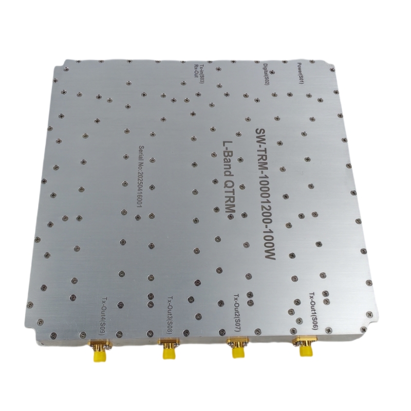
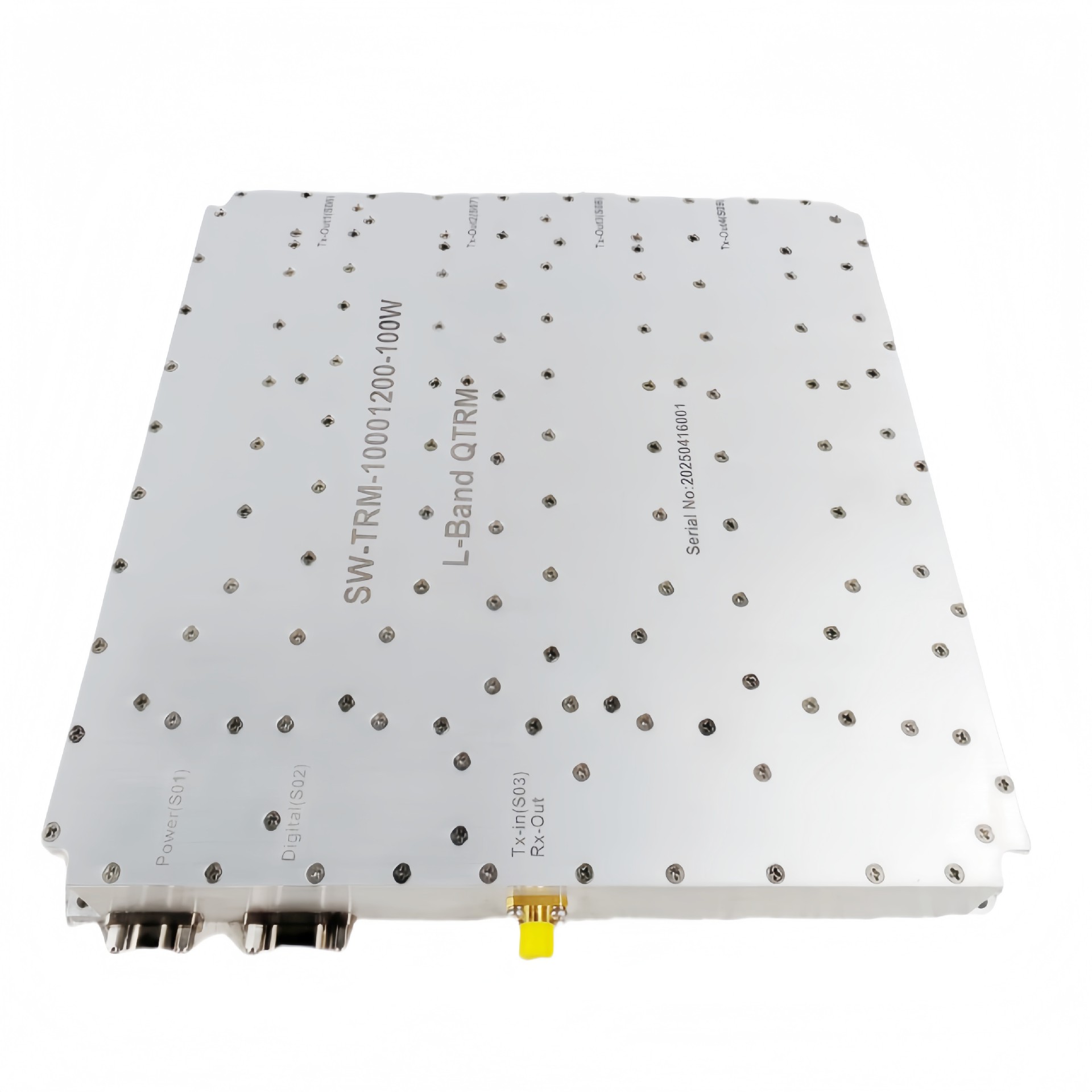
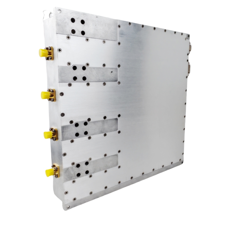
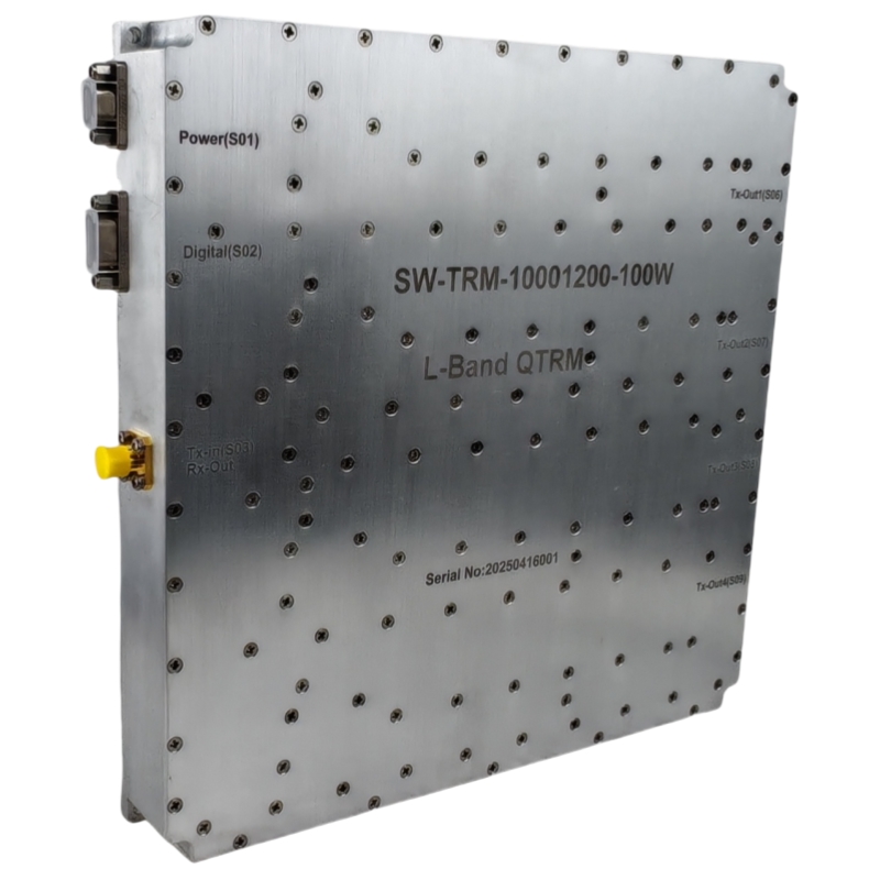
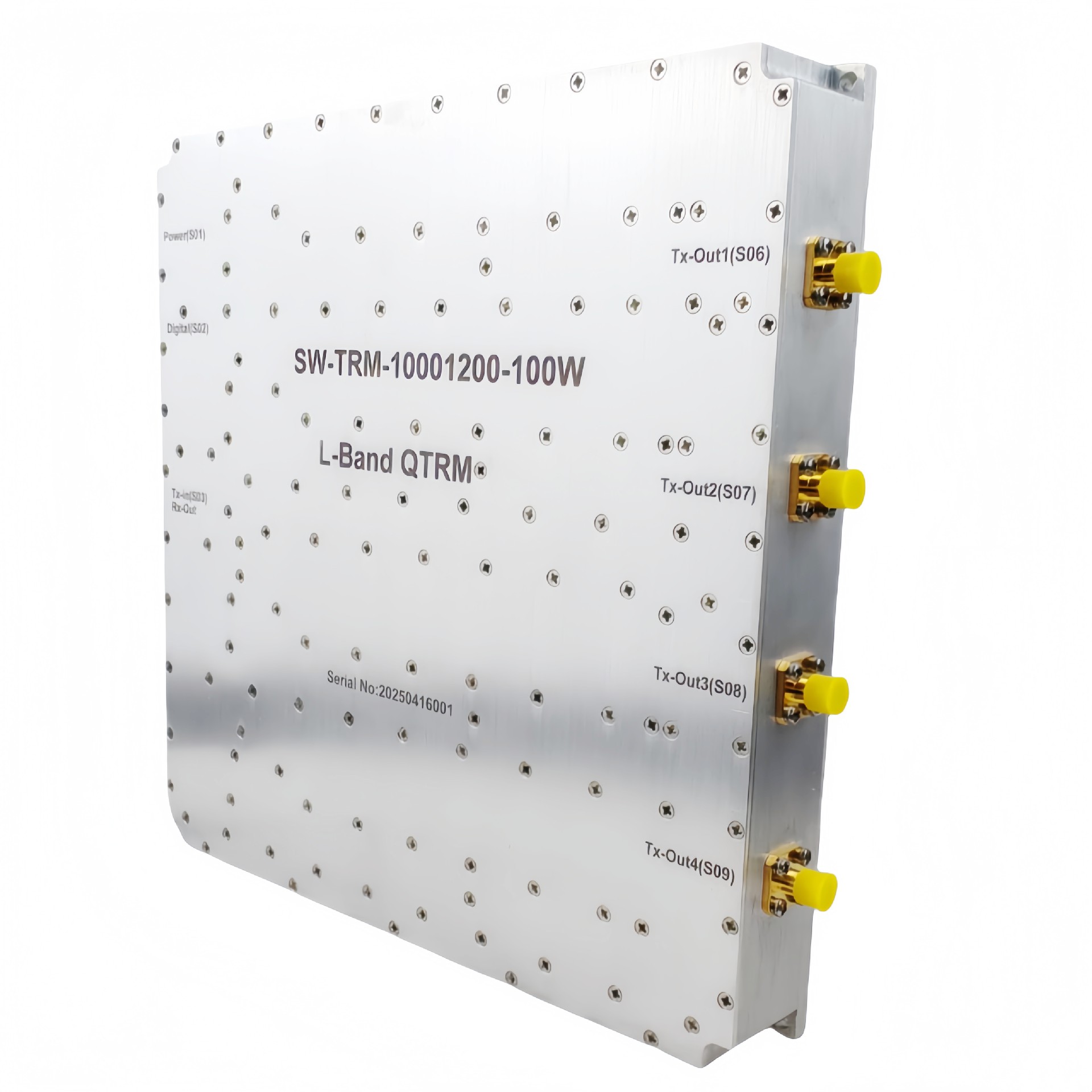
L-band TRM Module 1000-1200MHz 100W 4-Channel Phased Array Transceiver with RS422 Control for Radar/SATCOM
Place of Origin:China
Brand Name:SWT
Model Number:SW-TRM-10001200-50C-Diff RX
Price:Please Contact Customer Service
Product Description
Description
TRM stands for Tx /Rx Module, The module consists of 04 TX/RX Channel, TRM controller, Health Monitoring and Power supply card. The TRM will have single Tx / Rx input port and 4 output ports to be connected directly to antenna. Each Tx / Rx Channel will have independently controlled separate phase shifters and attenuators.
| RF / ELECTRICAL PARAMETER | ||||
|---|---|---|---|---|
| MIN | TYP. | MAX | UNIT | |
| Operating Frequency | 1000 | 1200 | MHz | |
| No. of Tx / Rx Channel | 4 | |||
| Peak Output Power / Channel | 50 | 51 | dBm | |
| Transmit Gain @ In all frequency/temps. | 53 | 54 | dB | |
| Tx input Power | -3 | dBm | ||
| Pulse Width | 2 | 50 | us | |
| Max Duty Cycle | 10 | % | ||
| Fall Time | 200 | ns | ||
| Raise Time | 500 | ns | ||
| TR switching time | 1 | us | ||
| Two channel switching time | 200 | ns | ||
| Tx Input VSWR | 1.5:1 | |||
| Rx Input VSWR | 2:1 | |||
| Rx Gain @ In all frequency/temps. | 26 | 27 | 28 | dB |
| Rx Output P1dB | +10 | dBm | ||
| Rx Noise Figure | 2 | dB | ||
| Phase shifter | 6 bits | 360° | ||
| Attenuator | 6 bits | 31.5 dB | ||
| Max. Rx tolerable power | 80-watt peak, 10% duty cycle | PWMax=50 usec | ||
| Max. beam switching time | 10 | usec | ||
| Phase variations over attenuator changes | ≤15° | 31.5 dB variation | ||
| Gain variation over phase shifter changes | ≤1 dB | 360° phase shifter change | ||
| Channel Isolation | 80 | dB | ||
| Power Supply | 28 | V DC | ||
| Average power consumption | 300 | W | ||
| Average currents | 6 | A | ||
| Peaking currents | 44 | A | ||
| Diff Rx OUT Channel | 1 |
| MECHANICAL | ||
|---|---|---|
| MECHANICAL PARAMETER | VALUE | UNIT |
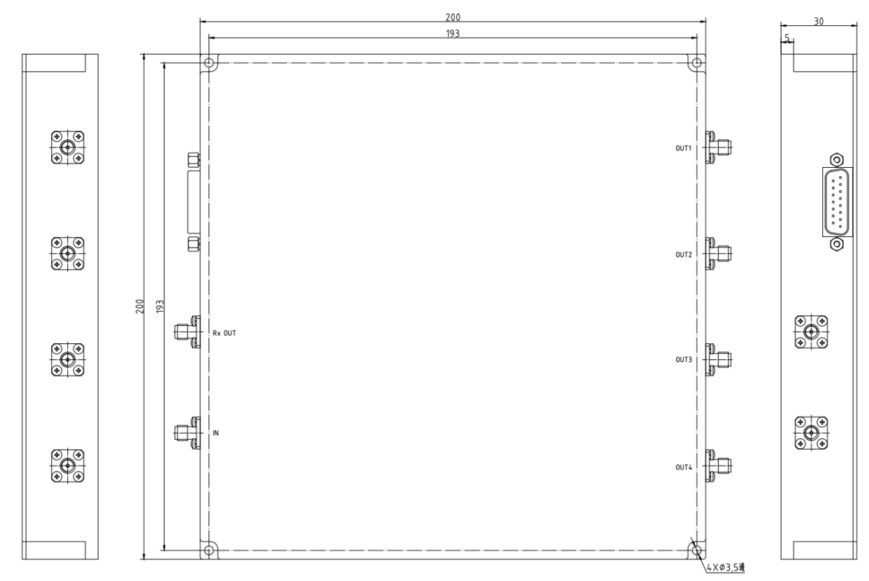
| Dimensions (L x W x H) | 200 x 200 x 30 | mm |
| RF Connectors (Input / Output) | SMA-K | -- |
| DC /Control Connector | DB15 - Type | -- |
| Cooling | Air Cooled (Not Supplied) | -- |
| Mounting | 3-4 Thru Hole | -- |
| Weight | ≤3 | kg |
| ENVIRONMENTAL / PROTECTIONS PARAMETER | MIN | MAX | UNIT |
|---|---|---|---|
| Operating Temp. (Housing Temp.) | -40 | +60 | °C |
| Humidity Range | 0 | 100 | % |
| PA Baseplate Shutoff Temperature | +70 | °C |
| FUNCTIONS / INTERFACE PARAMETER | MIN | MAX | UNIT |
|---|---|---|---|
| Additional Options | 1. VSWR Monitoring 2. Power Monitoring (Input & Output) 3. Transmit Enable/Disable 4. Input/output open, short protection 5. Temp Monitoring 6. Monitoring of voltage and current of each channel 7. 4 channels power supply and RF circuits are independent | ||
| Communication Protocol | 1. 4 bit Address code for TRM 2. RS422 Serial Link (5 MBPS) 3. Packet Format to be decided | ||
| Beam / PRF Trigger | Differential RS422 | ||
| AMPLIFIER CONNECTOR TYPE: | DB15-M | |
| TRIAD CABLE PART NUMBER: | -- | |
| NUMBER | Definition | DESCRIPTION |
|---|---|---|
| 1-3 | VDD | +28V |
| 4-6 | GND | GND |
| 7 | PA Enable | TTL Hi= Enable, TTL Lo = Disable or No Connection |
| 8 | GND | GND |
| 9 | Tx+ | RS422 serial bus interface (Channel selection, switches, parameter settings, status monitoring) |
| 10 | Tx- | |
| 11 | Rx+ | |
| 12 | Rx- | |
| 13-15 | NC | NC |
Product Details
Packing:
L-band TRM Module 1000-1200MHz 100W 4-Channel Phased Array Transceiver with RS422 Control for Radar/SATCOM
Power Consumption:
1000-1200MHz
Data Format:
100W
Working Temperature:
53~54 dB
Physical Interface:
1.5:1
Communication Interface:
±0.5 dB
Receiving Signal:
-40~--60
Applications:
-10~-20
Payment & Shipping Terms
Minimum Order Quantity
1/pcs
Packaging Details
Standard Packing
Delivery Time
5-8 work days
Payment Terms
L/C, D/A, D/P, T/T, Western Union, MoneyGram
Supply Ability
100pcs per month
Send Inquiry

ADD:Rooms 405 & 406, 4th Floor, Building 2, Big Data Industrial Base, No. 180 Software Avenue, Yuhuatai District, Nanjing, Jiangsu Province, China
+86 17302591509
+86-25-87702669
Contat Us
Copyright © 2026 Nanjing Shinewave Technology Co., Ltd. All Rights Reserved. PRIVACY POLICY