
 English
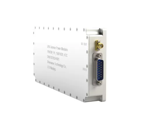
1560 - 1620MHz UAV Jammer Power amplifier 50W RF Amplifier Module
Place of Origin:China
Brand Name:SWT
Model Number:SW-UAV Jammer-15601620-47C
Price:
Product Description
UAV Jammer Power Amplifier 1560-1620 MHZ 50 W RF Power Amplifier
Description
The module is designed for both military and commercial applications. The latest device technologies and design methods are employed to offer high power density, efficiency, and linearity in a small, lightweight package.
Specification
Specifications subject to change without notice. Typical performance at +28VDC +25oC, and in a 50Ω system.
| RF / ELECTRICAL | ||||
| PARAMETER | MIN | TYP. | MAX | UNIT |
| Operating Frequency | 1560 | 1620 | MHz | |
| Output Power Psat | 47 | dBm | ||
| Power Gain Flatness | ±1 | dB | ||
| Gain·Adjust·Range | 32 | dB | ||
| Gain·Adjust·Step | 2 | dB | ||
| Operating Voltage | 28 | VDC | ||
| MECHANICAL | ||
| PARAMETER | VALUE | UNIT |
| Dimensions (L x W x H) | 170*90*25 | mm |
| RF Connectors (Output) | SMA-KFD | -- |
| DC Connector | DB15 | -- |
| Cooling | Baseplate Conduction - Optional Heatsink Available | -- |
| Mounting | 3-4 Thru Hole | -- |
| Weight | ≤1.5 | kg |
| ENVIRONMENTAL / PROTECTIONS | |||||||
| PARAMETER | MIN | MAX | UNIT | ||||
| Operating Temp. (Housing Temp.) | -20 | +50 | °C | ||||
| Humidity Range | 0-100 | % | |||||
| PA Baseplate Shutoff Temperature | + 80 | °C | |||||
| INPUT/OUTPUT PINS | |||||||
| AMPLIFIER CONNECTOR TYPE: | DB15 | ||||||
| TRIAD CABLE PART NUMBER: | —— | ||||||
| PIN NUMBER | LABEL | DESCRIPTION | |||||
| 1 | Amp Enable | TTL Hi= Enable, TTL Lo = Disable or No Connection | |||||
| 2 | GND | GND | |||||
| 3 | Forward power monitoring | Analog voltage relative to forward power 0 V to 3.3 V | |||||
| 4 | Reflected power monitoring | Analog voltage relative to reverse power 0V to 3.3 V | |||||
| 5 | Temp Monitoring | Analog voltage relative Temperature to power 0V to 3.3 V | |||||
| 6 | Temperature Alarm | Temperature Power Detection(TTL Hi= Normal , TTL Lo = Fault ) | |||||
| 7 | Current Monitoring | Analog voltage relative Monitoring to power 0V to 3.3 V | |||||
| 8 | REV Alarm | Reverse Power Detection(TTL Hi= Normal , TTL Lo = Fault ) | |||||
| 9 | PIN | Gain·Adjust·Range V1 | |||||
| 10 | PIN | Gain·Adjust·Range V2 | |||||
| 11 | PIN | Gain·Adjust·Range V3 | |||||
| 12 | PIN | Gain·Adjust·Range V4 | |||||
| 13 | PIN | Gain·Adjust·Range V5 | |||||
| 14-15 | VDC | +28V | |||||
Product Details
Name:
1560 - 1620MHz RF Power Amplifier
Operating Frequency:
1560 - 1620MHz
Psat Output Power:
50W
Gain:
47dB
Input Vswr:
2
Power Gain Flatness:
±1dB
Spurious Signals:
Harmonic Signals:
Operating Temp:
-20~50°c
Application:
UAV
Transport Package:
Carton
Specification:
170*90*25mm
Payment & Shipping Terms
Minimum Order Quantity
1/pcs
Packaging Details
Standard Packing
Delivery Time
5-8 work days
Payment Terms
L/C, D/A, D/P, T/T, Western Union, MoneyGram
Supply Ability
100pcs per month
Send Inquiry