
Abstract: With the widespread application of Unmanned Aerial Vehicle (UAV) countermeasure equipment in the security field, incidents of interference with shipborne Automatic Identification System (AIS) signals occur from time to time, seriously affecting ship navigation safety and maritime supervision. Combining a case of AIS signal interference, this paper analyzes the working principle of UAV countermeasure equipment and its impact on maritime traffic safety, explores the abnormal characteristics of AIS signals under such interference, summarizes monitoring and troubleshooting methods for such interference, and proposes suggestions on strengthening equipment supervision. The aim is to build a safe and reliable waterborne radio communication environment and ensure the safety of maritime navigation.
I. Introduction
With the continuous maturity of UAV technology and the rapid development of related industries, their application in various social fields is becoming increasingly widespread. However, this has also brought a series of safety hazards. Incidents of "unauthorized flights" causing accidents are common, posing a certain degree of threat to public security. To meet the needs of security, stability maintenance, and safe production, UAV countermeasure equipment has emerged. As required by relevant departments, UAV countermeasure equipment is widely deployed in important areas such as ports, oil depots, and nuclear power plants, as well as during key periods and for major event security, to prevent and respond to various UAV intrusion incidents. However, most of these devices work by interfering with radio signals or blocking control channels. Their operational range and impact boundaries are difficult to precisely control. Improper application or illegal use can cause interference to the surrounding electromagnetic environment and other radio communication services. Among these, interference with GPS signals is particularly harmful. In areas like ports, it can lead to abnormalities in the ship's Automatic Identification System (AIS) signals, subsequently affecting ship navigation safety and the supervision of maritime management agencies. Therefore, the standardized, effective, and reasonable use of UAV countermeasure equipment is particularly important.
I. Case Study of UAV Countermeasure Equipment Interfering with AIS Signals
On January 3, 2024, technicians from the Fuzhou Communication Center of the East China Sea Maritime Safety Administration discovered during an electronic patrol of vessels within their jurisdiction that the AIS signals of ships berthed at a port terminal appeared on land. The AIS trajectory showed obvious abnormalities, leading to suspicion of interference in the area.
Technicians from the Fuzhou Communication Center immediately went to the site to investigate the interference source. Using a PR200 handheld radio monitoring receiver, they detected an interference source emitting from the terminal. The affected frequency band was 1565 MHz ~ 1575 MHz, close to GPS frequencies, causing positioning errors for ship GPS/AIS (GPS frequencies: L1 at 1575.42±1.023 MHz, L2 at 1227.6±10.23 MHz, L5 at 1176.45±12 MHz; AIS equipment uses VHF channels 87B and 88B for signal transmission/reception, at 161.975 MHz and 162.025 MHz respectively).
Through communication with on-site personnel, it was learned that two sets of UAV countermeasure equipment were installed within the factory area. Technicians tested the interference from these two devices and ultimately confirmed them as the sources of GPS and AIS signal interference.
Based on the configuration of the UAV countermeasure equipment, technicians established a test route within the factory area. The specific test process was as follows: (1) Use a GPS receiver to collect position information changes when the UAV countermeasure equipment was transmitting normally and when transmission was stopped, comparing and analyzing its impact on GPS data. (2) Collect changes in the AIS trajectories of nearby ships when the UAV countermeasure equipment was transmitting normally and when transmission was stopped, comparing and analyzing its impact on ship AIS data.
Analysis of the collected data yielded the following results:
(1) When the UAV countermeasure equipment stopped transmitting, technicians moved from the terminal to the factory area carrying a GPS receiver. The GPS trajectory is shown in Figure 1, where the yellow markers represent the trajectory line drawn based on data collected by the GPS receiver. The GPS trajectory appeared normal. Simultaneously, the AIS trajectories of berthed ships were essentially at fixed points, consistent with reality; AIS data appeared normal.
(2) When the UAV countermeasure equipment was transmitting, technicians moved from the factory area to the terminal carrying a GPS receiver. The GPS trajectory is shown in Figure 2, where the red markers represent the trajectory line based on the GPS receiver data, and blue is the actual movement route. The GPS trajectory showed abnormal changes. The AIS trajectories of berthed ships are shown in Figure 3; the AIS trajectories exhibited abnormal changes, significantly shifting onto land areas, indicating abnormal AIS data.
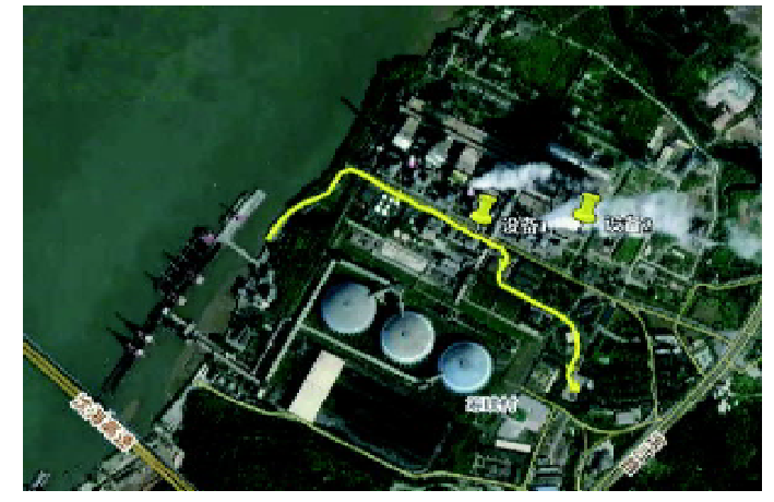
Figure 1: GPS Trajectory Change When UAV Countermeasure Equipment Transmission Stopped
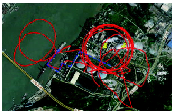
Figure 2: GPS Trajectory Change When UAV Countermeasure Equipment Was Transmitting
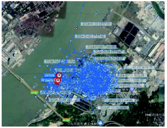
Figure 3: AIS Trajectory Change When UAV Countermeasure Equipment Was Transmitting
III. Working Principle of UAV Countermeasure Equipment
UAV countermeasure equipment is a technical device designed to counter unauthorized or malicious UAV flights. Its working principles mainly involve physical interference and electromagnetic interference. Examples include deploying nets to capture UAVs, using high-power microwaves or laser weapons to directly destroy UAVs, emitting high-power radio waves to jam or block UAV communication links, or transmitting false GPS signals to cause UAV positioning errors.
The mainstream working modes of UAV countermeasure equipment on the current market include radio detection, passive detection and positioning, TDOA (Time Difference of Arrival), RID (Remote ID) protocol monitoring, radio interference countermeasures, and radio jamming. Their targets are UAV video transmission, flight control links, and navigation signals. The operating frequency band ranges from 100 MHz to 6 GHz. Some devices operate at fixed frequency bands, such as 900 MHz, 1.2 GHz, 2.4 GHz, 5.2 GHz, 5.8 GHz, etc., which are common UAV frequency bands. UAV countermeasure equipment based on navigation spoofing operates in the GPS L1 and GLONASS L1 bands. This paper primarily discusses UAV countermeasure equipment using radio countermeasure technology. Based on different radio mechanisms, countermeasure techniques can be further divided into suppressive jamming and deceptive jamming.
UAV flight parameters such as trajectory, speed, altitude, and heading all require ground remote control. Suppressive jamming involves, after obtaining information like the UAV's remote control link frequency band, transmitting interference signals at the same frequency but with power significantly greater than the GPS signal power. This cuts off normal communication between the UAV and the ground control station, depriving the UAV of its ability to obtain position, speed, time, and other information from GPS satellites. This then triggers the UAV's self-protection system, forcing it to autonomously return, hover, or land.
Deceptive jamming involves transmitting signals similar to GPS signals, forcing the satellite navigation system to receive and calculate pseudo-navigation signals. This causes the UAV to obtain false position, speed, and time information. Deceptive jamming can be further divided into repeater spoofing and generative spoofing. The former delays, modulates, and amplifies intercepted GPS signals before retransmitting them to the target, confusing the positioning result. The latter calculates parameters such as the required code phase delay, carrier Doppler shift, and navigation message needed to simulate a pre-specified position, then generates false signals recognizable by GPS receivers, inducing them to track and acquire this signal, resulting in erroneous positioning information.
IV. Impact of UAV Countermeasure Equipment on Maritime Traffic Safety
While interfering with UAV signals, UAV countermeasure equipment also affects the surrounding radio order. Since navigation satellites are as high as 20,200 km above the ground, when the signal propagates to the ground receiver, its strength is already very weak, typically even lower than environmental noise. Especially when such equipment transmits high-power signals, the background noise floor is significantly raised, making GPS signals extremely vulnerable to interference. AIS is an aid-to-navigation system that enables information sharing between ships and ships, and ships and shore. The GPS receiver is a key component, providing positioning, timing, and calculating speed and heading. The AIS system, in conjunction with GPS, automatically broadcasts the ship's dynamic information (position, speed, heading) combined with static information (ship name, call sign, Maritime Mobile Service Identity - MMSI) via VHF to nearby vessels [2]. The widespread application of AIS systems on ships has provided a guarantee for maritime navigation safety and has become one of the primary means for regulatory authorities to monitor vessel movements. Therefore, once GPS signals are interfered with, information such as ship position, course, and speed becomes abnormal, subsequently affecting vessel identification, collision avoidance, and navigation, posing safety hazards to ship navigation.
The normal operation of maritime traffic support service systems relies on a good maritime electromagnetic environment. At the same time, the signal coverage of maritime communication and traffic control equipment is highly directional and sensitive. If the operational area of UAV countermeasure equipment overlaps with these devices, or worse, if high-power, full-band interference is used, it will not only affect UAV remote control links but also reduce the ability of these devices to process communication, navigation, and surveillance signals. This severely impacts maritime supervision and waterborne traffic safety.
V. Analysis of AIS Signal Anomalies Under UAV Countermeasure Equipment Interference
Due to limitations, this paper selects only common UAV countermeasure equipment based on radio detection and navigation spoofing for analysis. The test results above show that GPS interference from such equipment causes AIS signals to exhibit the following characteristics:
(1) GPS Positioning Anomaly: Due to the interference signal emitted by the UAV countermeasure equipment covering the GPS band, it suppresses the reception of satellite navigation signals or induces the reception of deceptive signals, leading to GPS positioning anomalies. In this situation:
* AIS may exhibit positioning drift: The ship's displayed AIS position deviates significantly from its actual position, jumping randomly or drifting slowly on the chart.
* AIS may experience positioning loss: The AIS cannot acquire GPS signals, leading to interrupted position information, displaying "no data" or the last known position.
(2) AIS Dynamic Information Failure: Since GPS is the core source of AIS dynamic data, if UAV countermeasure equipment interference prevents AIS vessel dynamic data from updating, the AIS dynamic information (position, speed, heading, etc.) stagnates or displays erroneous values (e.g., speed 0, abnormal heading). Other vessels or shore-based systems cannot track the ship's real-time status via AIS. One reason is that UAV countermeasure equipment generates broadband harmonics or electromagnetic interference that pollutes the AIS channel, causing AIS message transmission interruptions or check failures (e.g., CRC errors). Other ships' AIS terminals cannot parse the AIS dynamic information, displaying the target as "unknown status" or experiencing frequent flickering/disconnections.
(3) AIS Static/Voyage Information Error: AIS requires strict time synchronization (UTC time). Some AIS devices use GPS time as the data synchronization reference (timestamp). Once GPS is interfered with, time synchronization is disrupted. If GPS timing is interrupted, the AIS cannot broadcast dynamic information at standard intervals (e.g., every 2-10 seconds). Simultaneously, incorrect timestamps may cause data packets to be considered "stale" and ignored by other ships or shore-based systems.
(4) AIS System Alarms and False Alarms: Most civilian ship AIS equipment is not configured with multi-mode GNSS (e.g., GPS+BeiDou+GLONASS) or inertial navigation redundancy. Once GPS is jammed, the system lacks a backup positioning solution and triggers a "GPS signal lost" alarm.
VI. Monitoring Methods for AIS Signal Interference Sources
Once out of control, UAV countermeasure equipment will negatively impact the AIS navigation environment. Effectively determining the location of interference sources has become a challenge for maritime and navigation safety authorities. In practice, identifying signal interference sources requires combining technical means for on-site investigation and multi-party collaboration.
1) Preliminary Determination of Interference Type: Before locating the interference source, the nature of the interference needs to be clarified. This includes:
* Persistent Interference: Present around the clock, possibly from fixed facilities like illegal transmitters or industrial equipment.
* Intermittent Interference: Occurs during specific periods, potentially related to UAV countermeasure equipment or temporary communication activities.
* Localized Interference: Only affects specific areas, such as ports or narrow channels. The case described above is a typical example of intermittent and localized interference.
(2) Technical Detection and Location Tools: Primarily involve monitoring using spectrum analyzers, directional antennas, and direction-finding equipment. Common spectrum analyzers include portable spectrum analyzers (e.g., Rigol DSA815) and SDRs (Software Defined Radio) with spectrum functionality.
* First, tune the device to the AIS frequency bands (161.975 MHz and 162.025 MHz).
* Second, observe the signal spectrum characteristics. Normal signals are periodic pulses, every 2-10 seconds. Interfered signals manifest as continuous noise, fixed-frequency spikes, or abnormal modulation waveforms.
* Finally, the interference direction can be judged by changes in signal strength (RSSI).
Additionally, directional antennas and direction-finding equipment like Yagi antennas or Doppler direction finders can be used. Directional antennas exploit the directionality of received signal strength to locate the interference source. By measuring interference signal strength at multiple positions, the approximate bearing of the source can be determined, typically using triangulation to find the intersection point.
(3) Mobile Monitoring: Drive a vessel or vehicle carrying a portable spectrum analyzer around the suspected area, recording the locations of signal strength peaks. Combine with charts/maps to mark signal strength distribution and narrow down the interference source range.
(4) Data Cross-Validation: Deploy multiple AIS receivers at different locations to record interference phenomena during the same time period. Analyze the coverage area and intensity gradient of the interference signal to further narrow down the source location.
(5) Interference Source Feature Analysis: Due to subtle manufacturing differences, the internal circuits of communication emitters have hardware variations, causing their transmitted signals to exhibit unique characteristics distinguishing them from other individual emitters. This is known as the signal fingerprint [3]. Utilizing signal fingerprint recognition technology allows identification of different individual emitters of the same model for signal tracking and monitoring. For example, track the interference source modulation: AIS uses GMSK modulation; interference signals might use other modulations (e.g., FM, AM). Big data matching can also be used to compare against a known interference source feature database (e.g., industrial equipment, illegal repeaters) to see if the signal characteristics after interference match those of known sources in the database.
VII. Suggestions for Strengthening Supervision of UAV Countermeasure Equipment
(1) Improve Laws and Regulations:
Article 22 of the newly revised "Maritime Traffic Safety Law of the People's Republic of China" stipulates, "No unit or individual may damage maritime traffic support service systems or hinder their working efficiency." Article 23 stipulates, "The competent transport department of the State Council shall organize the construction of maritime radio monitoring systems within its system (industry) and monitor their radio signals, and maintain maritime radio wave order together with the national radio regulatory agency." This grants transportation management departments the authority to regulate waterborne radio order. However, relevant industry standards and management specifications have not yet been formally established. Further supporting policies or guidelines for UAV countermeasure equipment need to be issued, such as formulating "Regulations on the Management of UAV Countermeasure Equipment."
(2) Formulate Industry Standards:
In the R&D, design, and production phases, establish testing standards for equipment safety, quality reliability, and environmental adaptability to form unified technical standards and specifications for equipment manufacturers. Simultaneously, promote the R&D of spectrum isolation technology between UAV countermeasure equipment and critical infrastructure (e.g., AIS systems, aviation navigation systems) to reduce indiscriminate interference.
In the usage phase, formulate corresponding usage specifications for different control objects, usage scenarios, and service frequency bands. This ensures both that countermeasure needs are met and that other waterborne radio services operate normally and orderly. Furthermore, incorporate UAV countermeasure equipment into special equipment management, clearly defining restrictions on the user entity, usage time, location, and transmission power in sensitive areas, important public places, and major event zones.
(3) Strengthen System Construction:
Establish maritime radio monitoring systems in important sea areas. Based on different application requirements, deploy radio spectrum monitoring stations to monitor abnormal signals in real-time and enable automatic alarms. Simultaneously, integrate multi-dimensional supervision data from AIS, radar, image recognition, etc., to manage UAV countermeasure equipment from the perspectives of equipment management, personnel support, and practical application, enhancing maritime supervision capabilities. Also, strengthen waterborne radio signal monitoring and protective monitoring of relevant frequency bands to prevent UAV countermeasure equipment from affecting, occupying, or illegally blocking maritime radio dedicated frequencies.
(4) Strengthen Application Supervision:
Establish and improve supervision and inspection mechanisms. Urge installation units to register with local radio management agencies before using UAV countermeasure equipment. Strengthen supervision and auditing of equipment sales channels and product information. UAV countermeasure equipment can be connected to a supervision platform to report usage time, location, and operating frequency bands in real-time. Strengthen guidance and standardization of equipment usage. Reasonably plan installation locations based on full consideration of the surrounding electromagnetic environment. Conduct radio monitoring based on actual conditions to grasp equipment usage and assess impact levels. Adjust parameters like transmission power and coverage area when necessary to avoid interference with other radio services. Simultaneously, establish a multi-departmental joint working mechanism involving maritime, navigation safety, radio regulation, fisheries, public security, etc. Strengthen joint supervision, prevention, and law enforcement across the equipment production, R&D, purchase, sales, transportation, and usage stages. Enable rapid location, evidence collection, and handling of interference incidents, increasing supervision and investigation efforts to achieve whole-process management from source governance to end-point control.
VIII. Conclusion
Strengthening the management of maritime radio order is an important measure to ensure efficient, orderly, and safe maritime communication. It is also the foundation and support for safeguarding maritime traffic safety and maintaining national maritime security. As UAV countermeasure equipment gradually becomes indispensable security equipment for protecting important areas and major events, it is essential to strengthen scientific supervision over the R&D, production, sales, and use of such equipment. Concerted efforts are needed to curb the spread of unauthorized installation or misuse. We must both effectively maximize the utility of the equipment and reasonably solve the problem of waterborne radio interference, striving to maintain an orderly, safe, and reliable waterborne radio communication environment to safeguard the navigation safety of maritime vessels.
 Analysis and Considerations on AIS Signal Interference Caused by UAV Countermeasure Equipment.pdf
