
 English
1. Radar RF System Architecture and Block Diagram
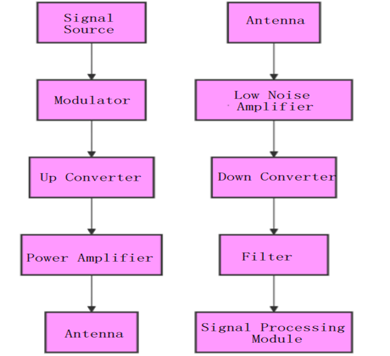
1.1 Transmitter Structure
Signal Source: Generates baseband or modulated signals for radar waveform generation (such as linear frequency modulation waves, pulse waves, etc.).
Modulator: Modulates the baseband signal into an RF signal.
Upconverter: Converts the signal to the operating frequency band.
Power Amplifier: Amplifies the RF signal, providing sufficient output power to be transmitted to the antenna.
Antenna: Radiates the amplified RF signal into the air to cover the target area.
1.2 Receiver Structure
Antenna: Receives the target echo signal.
Low Noise Amplifier (LNA): Amplifies the weak echo signal, improving the signal-to-noise ratio.
Downconverter:Converts the high-frequency signal to an intermediate frequency.
Filter: Extracts target frequency signals while suppressing noise.
Signal Processing Module: Demodulates, detects, and analyzes the echo signals.
2. Classification of Different Types of Radars
Radar systems can be classified based on their function and frequency bands:
2.1 Classification by Function
Surveillance Radar: Used for wide-area target search and monitoring.
Tracking Radar: Focuses on the precise tracking of a single target.
Imaging Radar: Such as Synthetic Aperture Radar (SAR), used to generate high-resolution images of targets.
Weather Radar: Used to detect weather conditions such as rainfall intensity, wind speed, and direction.
Fire Control Radar: Used in weapon systems for target tracking and engagement.
Vehicle-Mounted or Airborne Radar: Used for navigation and environmental awareness in vehicles or aircraft.
2.2 Classification by Frequency Band
L-band (1–2 GHz): Suitable for long-range surveillance and weather radar.
S-band (2–4 GHz): Used for airborne and maritime surveillance.
C-band(4–8 GHz): Suitable for weather and medium-range surveillance.
X-band (8–12 GHz): Used for precision target tracking and imaging radar.
Ku-band (12–18 GHz): Used for high-resolution imaging radar.
Ka-band (26.5–40 GHz): Used for short-range, high-resolution applications.
Millimeter-Wave Band (Above 40 GHz): Used for ultra-high-resolution short-range radar systems.
3. Power Amplifier Requirements and Frequency/Power Allocation in Radar Systems
The power amplifier is a key component at the transmitter end of radar systems, and its performance directly impacts the radar’s detection range, accuracy, and stability. The main requirements include:
3.1 Frequency Range
The power amplifier must cover the frequency bands used by the radar, such as:
L-band: 1–2 GHz
X-band: 8–12 GHz
Ka-band: 26.5–40 GHz
3.2 Output Power
Output power determines the radar’s maximum detection range:
Low-Power Amplifier: 10 W – 100 W, used for short-range radar.
Medium-Power Amplifier: 100 W – 1 kW, used for medium-range radar.
High-Power Amplifier: Above 1 kW, used for long-range surveillance radar.
3.3 Efficiency
High-efficiency amplifiers reduce power consumption and heat generation, suitable for continuous operation environments.
3.4 Linearity
High linearity ensures reduced signal distortion and improves the accuracy of echo signal processing.
3.5 Size and Weight
For airborne or vehicle-mounted radar systems, the power amplifier must be compact and lightweight.
4. How to Select Power Amplifiers in Radar Systems
4.1 Key Points for Selecting Power Amplifiers
Frequency Compatibility: Choose a suitable power amplifier based on the radar’s operating frequency band, such as an X-band amplifier for precision tracking radar.
Power Requirements: Determine the required output power based on the radar’s detection range and purpose.
Linearity Requirements: Ensure the amplifier has sufficient linearity to minimize signal distortion, especially in high-resolution radars.
Thermal Management Performance: Ensure the amplifier is designed with effective heat dissipation capabilities to handle high power output.
4.2 Considerations When Using Power Amplifiers
Input Signal Control: Ensure the input signal is within the allowable range to avoid nonlinear distortion or damage to the equipment.
Thermal Management: For high-power applications, an efficient cooling system (such as air cooling or liquid cooling) should be provided.
Reflection Power Protection: Prevent damage from reflected power caused by load mismatching.
Regular Calibration and Inspection: Perform regular maintenance and performance checks to ensure long-term stable operation of the amplifier.
5. Common Power Amplifier Frequency Bands and Power
5.1 L-band Amplifiers
Frequency Range: 1–2 GHz
Output Power: 10 W – 1 kW
Application: Long-range surveillance radar.
5.2 X-band Amplifiers
Frequency Range: 8–12 GHz
Output Power: 50 W – 500 W
Application: High-precision target tracking radar.
5.3 Ka-band Amplifiers
Frequency Range: 26.5–40 GHz
Output Power: 10 W – 200 W
Application:Short-range, high-resolution radar.
5.4 Millimeter-Wave Amplifiers
Frequency Range: Above 40 GHz
Output Power: 1 W – 50 W
Application: Ultra-high-resolution imaging radar.
6. Conclusion
The radar RF system architecture includes core modules for both the transmitter and receiver, and its design must meet the requirements of different radar functions and frequency bands. The power amplifier is a key component in the radar system, and its performance affects the radar's detection range, accuracy, and stability. When selecting and using power amplifiers, it is essential to consider the specific application, taking into account frequency, output power, linearity, and efficiency to ensure efficient and reliable operation of the radar system.
