
 English
RF Passive Device Intermodulation Testing System
The RF passive device intermodulation testing system is used to evaluate whether passive components (such as cables, connectors, filters, etc.) will generate nonlinear effects, especially intermodulation distortion, under multi-signal high-power conditions. It simulates real-world operational environments and measures the intermodulation characteristics of passive devices to ensure their reliability in complex signal environments.
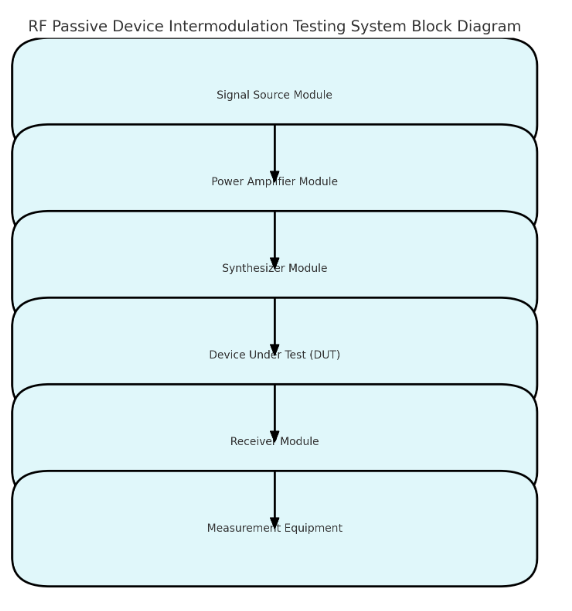
Test System Block Diagram Signal Source Module:
Provides multiple frequency high-power RF signals. The signal source is typically composed of two independent RF signal generators, each generating signals at two different frequencies.
Power Amplifier Module:
Amplifies the RF signals output by the signal source to the required power level for testing. Provides linear amplification to avoid interference from the amplifier's own nonlinearity in the test results.
Synthesizer Module:
Combines the two amplified signals and loads them into the Device Under Test (DUT). Ensures the phase relationship and power matching of the combined signals.
Device Under Test (DUT):
The test object, such as cables, connectors, filters, etc.
Receiver Module:
Receives the output signal from the DUT, and uses a high-sensitivity receiver to analyze the intermodulation components in the signal.
Measurement Equipment:
Uses a spectrum analyzer or intermodulation test instrument to detect the intensity and frequency location of the intermodulation signals.
Measurement Principle
The basic principle of passive intermodulation testing is to simultaneously apply two different frequency RF signals (f1 and f2) to the DUT. If the device exhibits nonlinearity, intermodulation components will appear in the output signal, such as:
Second-order intermodulation components: f1+f2, f1-f2.
Third-order intermodulation components: 2f1-f2, 2f2-f1.
Higher-order intermodulation components: 3f1-2f2, 3f2-2f1, and so on.
By measuring the power and frequency of the intermodulation components, the nonlinear characteristics of the passive device can be evaluated.
Power Amplifier Application
The power amplifier plays a crucial role in the passive intermodulation testing system, with its main applications including:
High-power signal generation:
The power amplifier amplifies the small power signals from the signal source to the required high-power levels (such as tens of watts to kilowatts), providing stable output power to ensure the accuracy of the intermodulation test.
Frequency range coverage:
Covers the operating frequency range of the DUT and supports broadband or ultra-wideband testing requirements.
High linearity amplification:
The amplifier needs to have excellent linearity to avoid introducing intermodulation distortion that would affect the test results.
Multi-channel application:
In tests requiring multiple signal inputs, a multi-channel power amplifier can support independent amplification of multiple frequency signals.
Ultra-Wideband Power Amplifier for Testing Different Frequency Bands
1. Characteristics of Ultra-Wideband Power Amplifiers
Wide frequency range: Typically covers frequency bands from tens of MHz to tens of GHz, suitable for testing various RF passive components.
High output power: Supports high-power testing, meeting the needs of passive components with high load requirements.
High linearity: Ensures no additional nonlinear distortion is introduced during the amplification process.
2. Implementing Testing Across Different Frequency Bands
Frequency point selection:
Choose the signal source frequency range according to the DUT's operating frequency band. The ultra-wideband power amplifier can support testing in both low frequencies (e.g., L-band) and high frequencies (e.g., Ka-band).
Multi-frequency signal generation:
Use multiple signal sources to generate signals at different frequencies, which are then amplified by the power amplifier and loaded into the DUT.
High-power loading:
Ensure that the amplified signals have enough power to test the passive components under actual high-power conditions.
Frequency band extension testing:
Ultra-wideband power amplifiers support continuous testing from low to high frequencies and can be used for intermodulation testing of wide-band passive components.
How to Select an Ultra-Wideband Power Amplifier
1. Key parameters selection
Frequency range:
Select an ultra-wideband power amplifier that covers the target frequency range according to the DUT's operating frequency band.
Output power:
Ensure that the amplifier's output power meets the test requirements for passive components. High-power testing requires amplifiers with hundreds of watts to kilowatts of capacity.
Linearity:
The amplifier must have high linearity to avoid interference from its own nonlinearity in the test results.
Heat dissipation performance:
High-power output requires an efficient heat dissipation system to ensure long-term stable operation of the equipment.
2. Considerations
Input signal protection:
Ensure that the input signal amplitude is within the power amplifier's input range to prevent damage to the device.
Calibration and verification:
Calibrate the power amplifier before testing to ensure its output power and frequency characteristics are accurate.
Reflection power management:
During testing, use isolators or load matchers to prevent reflected power from damaging the amplifier.
Conclusion
The RF passive device intermodulation testing system generates high-power signals through power amplifiers to evaluate the nonlinear characteristics of passive components in complex signal environments. Ultra-wideband power amplifiers provide a high-performance solution for intermodulation testing, enabling multi-frequency band testing from low to high frequencies. When selecting and using ultra-wideband power amplifiers, consider factors such as frequency range, output power, linearity, and heat dissipation performance to ensure accurate test results and system stability.
 rf_passive_intermodulation_testing_system.pdf